

Content last revised on September 10, 2026
Radiated Emissions Compliance and Backplate Grounding
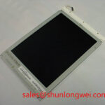
When evaluating the LM64P844 in an industrial HMI enclosure, begin with the physical signal path. Follow the display cable from the controller board to the panel connector, checking whether the flexible cable is routed alongside switching nodes, motor-drive conductors, relay wiring, or unshielded power wiring. In a marine bridge console, the display may share an enclosure with radar processing electronics, navigation equipment, DC converters, and communication interfaces. Those assemblies can create a difficult electromagnetic environment even when the LCD module itself is operating correctly.
The available factory data does not confirm whether this model uses TTL or LVDS signaling, so the original connector drawing and controller documentation must be treated as the authority. If the system uses a differential LVDS link, designers should preserve the intended pair arrangement, avoid unnecessary connector transitions, and keep the return path continuous through the enclosure. If the system uses a single ended TTL interface, the grounding and cable strategy will be different. The exact electrical interface should never be inferred from the TFT LCD package description alone.
A backplate grounding scheme can be assessed by examining how the display frame, cable shield, controller ground, and enclosure bonding points are connected. A multi point grounding arrangement may help control high frequency common mode current when it is implemented with a deliberate current return path. It can also create unwanted circulating currents if painted surfaces, anodized brackets, or long pigtail connections interrupt the intended path. This is a Design Consideration, not a factory EMC specification for LM64P844.
Common mode ferrite components may be evaluated when conducted or radiated noise is observed near the display cable, but their impedance behavior must be checked across the actual pixel clock spectrum and cable construction. An unsuitable component can increase signal edge distortion or reduce timing margin. The correct validation method is to compare the known good signal at the controller output and at the panel input while monitoring clock quality, data transitions, and displayed image stability across the intended temperature range.
The presence of horizontal bands, intermittent pixels, or image movement should not be assigned to one cause without measurement. Inspect connector retention first, then compare the signal path with a known good assembly. Check enclosure bonding, cable proximity to high current switching conductors, and the controller ground reference. CISPR Class A or Class B compliance belongs to the completed equipment and its installation, not to the individual LCD module as a standalone claim.
For a cross model evaluation, engineers may compare the mechanical and electrical documentation for LM64P10. That comparison should remain document based: connector position, active area, resolution, timing, power requirements, and backlight control must all be checked before any substitution decision.
Backlight Drive, Dimming, and Flicker Evaluation
The backlight arrangement is a critical part of an LCD replacement assessment. The available verified information for LM64P844 identifies the display category and package but does not specify whether the original assembly uses a particular LED or CCFL configuration, nor does it publish a confirmed current, ignition, dimming, optical contrast, or service life value. The system integrator should verify the required backlight technology and driver requirements from the original Sharp panel documentation.
Do not connect a replacement driver solely because its output connector appears similar. A constant current LED driver requires the correct load arrangement, enable behavior, dimming signal, and protection response. A CCFL system requires a compatible inverter and high voltage insulation arrangement. These are different electrical architectures, and the panel model description by itself does not establish which one is present in a particular equipment assembly.
When a WLED implementation is confirmed by the source documentation, the engineering review should cover current regulation, start up behavior, open load protection, thermal placement, and the relationship between PWM duty cycle and perceived brightness. A PWM frequency range or a 1000:1 dimming ratio should not be attributed to LM64P844 unless those values appear in the applicable factory specification. The controller designer should select a dimming strategy after checking camera exposure requirements, operator comfort, conducted noise, and the response of the actual backlight driver.
Flicker evaluation is best performed at several brightness settings rather than only at full output. Observe the panel with a high speed camera or a suitable photometric instrument while checking the enable line and dimming waveform at the driver. Audible noise should also be checked near the driver and enclosure panels, since mechanical vibration can originate in the power stage rather than in the LCD cell. A display that appears stable at the workbench can behave differently after installation beside a converter or other vibrating equipment.
Direct sunlight creates a separate readability problem. The original optical specification should be checked for luminance, contrast ratio, viewing direction, surface treatment, and allowable ambient illumination. A claim such as greater than 500:1 contrast at 50,000 lux is not established by the available LM64P844 information and should not be used as a purchasing assumption. For a marine console, assess the complete front assembly, including window material, seal, anti glare surface, viewing angle, and the effect of salt residue or condensation.
Power sequencing also deserves a bench test. Confirm the order in which logic power, backlight enable, video data, and display reset are applied. A temporary white screen, residual image, or failure to resume can result from controller timing, an inactive enable signal, or an incorrect reset relationship. The correct sequence is system specific and should be verified against the original panel and controller documentation.
Where the display is part of a larger Sharp related solution, engineers can review LMS700KF01-001 as a separate reference for coordinated display and power architecture. It should not be treated as an automatic companion or replacement for the LM64P844.
Frame Lag, Image Smearing, and Mechanical Stress
Before investigating image response, confirm that the replacement panel receives the correct timing format. Resolution, pixel clock, horizontal and vertical timing, data mapping, and signal polarity must match the controller configuration. The available factory record for LM64P844 does not provide those timing values, so they should be taken from the original Sharp data sheet or the equipment service documentation. JEIDA and VESA data mapping are not interchangeable assumptions; the controller must be configured for the format required by the installed panel.
Image smearing can be associated with panel response behavior, unsuitable timing, unstable supply rails, temperature, or a signal integrity problem. A cold storage installation may expose these differences more clearly because liquid crystal response changes with temperature. That general behavior is a Design Consideration, not a confirmed LM64P844 operating rating. The applicable temperature range, gray to gray response, and storage limits must be verified from the original factory specification.
Use a controlled test pattern containing dark to light transitions, fine text, moving bars, and medium gray areas. Compare the display at room conditions and at the intended environmental extremes only when the equipment test process provides suitable thermal control. Record whether the artifact follows the image content, changes with temperature, or changes when the cable is moved. This helps separate panel response from connector contact, timing instability, and mechanical interference without assigning a single unverified cause.
Flexible cable handling is equally important. Inspect the FPC or FFC for sharp creases, compression marks, contamination, and excessive tension at the connector entrance. The bend path should be supported by the enclosure design, with no force transferred to the connector latch after the display is secured. Repeated service access can reduce connection reliability if the cable is folded along the same crease or inserted at an angle. Connector locking force, cable orientation, and contact count must be checked against the original assembly drawing.
Vibration and shock testing should include the display bracket, bezel, controller board, and cable restraint as one mechanical system. A rigid bracket can transfer enclosure vibration directly to the glass assembly, while an overly flexible bracket can allow the connector to move during operation. Engineers should evaluate stress relief, fastener seating, panel flatness, and clearance around the viewing area. Any mounting torque used in production should come from the equipment design specification or fastener standard rather than being presented as an LM64P844 factory parameter.
Marine applications also require enclosure-level attention to sealing and condensation. The LM64P844 product description does not establish an ingress protection rating, salt fog qualification, conformal coating, or marine certification. The completed console should therefore be assessed for pressure equalization, moisture control, cable gland integrity, and the effect of cleaning chemicals. A panel replacement cannot independently confer certification on the equipment.
For broader display interface and troubleshooting context, the engineering principles in The Ultimate Guide to Industrial TFT LCD Technology can be used alongside the model specific documentation. During service, disconnect power before removing the display cable, and verify that stored energy in the backlight or power section has been discharged according to the equipment service procedure.
Surface Readability, Static Interfaces, and Long Term HMI Use
Inspect the LM64P844 front surface under the same lighting direction used by the operator. Reflections from bridge windows, chart lighting, instrument lamps, and protective covers can obscure a display even when the panel is functioning normally. The available verified data does not confirm an AG or AR coating, surface haze, viewing cone, TN, IPS, or MVA cell structure for this model. Those characteristics must be verified from the applicable Sharp documentation or from an approved sample evaluation.
Anti glare and anti reflective treatments solve different optical problems. An anti glare surface scatters reflected light and may change perceived sharpness, while an anti reflective treatment is intended to reduce reflected intensity through surface design. The final result depends on the panel, cover glass, optical bonding, bezel depth, and ambient geometry. A replacement should therefore be evaluated inside the actual console rather than judged only from a loose panel on a workbench.
Viewing angle testing should use the real operator position and the most frequently displayed information. Do not assume a symmetric viewing cone such as 85 degrees in every direction unless it is printed in the model specification. TN grayscale inversion, color shift, and contrast loss can affect radar controls or navigation status fields when the display is viewed from below, above, or from the side. The system owner should define the acceptable readability window for the installed equipment.
Long term static HMI screens also need software and operational consideration. Repeatedly displaying the same status bar, alarm region, or navigation symbol can produce uneven visual aging or temporary image retention depending on the panel technology and drive conditions. The available LM64P844 information does not provide a burn in guarantee, retention limit, or lifetime prediction. Designers may consider screen rotation, controlled brightness, automatic dimming, and periodic layout variation where the application permits, then validate the result on the actual panel under representative duty.
Brightness control should be calibrated at the system level. The controller, backlight driver, cover window, ambient sensor, and user interface all influence perceived luminance. PWM linearity should be measured rather than assumed, especially when low brightness is needed during night navigation. Check for visible modulation, camera banding, acoustic noise, and unexpected brightness steps while the panel is installed in its final enclosure.
Before approving the LM64P844 for a replacement build, retain a record of the verified model marking, connector drawing, interface format, backlight requirements, mechanical dimensions, environmental limits, and power sequence. These checks provide the evidence needed to distinguish a mechanically suitable display from a complete electrical and optical match for the target HMI assembly.

