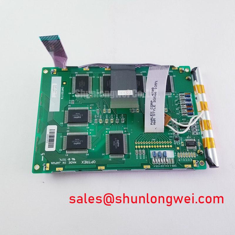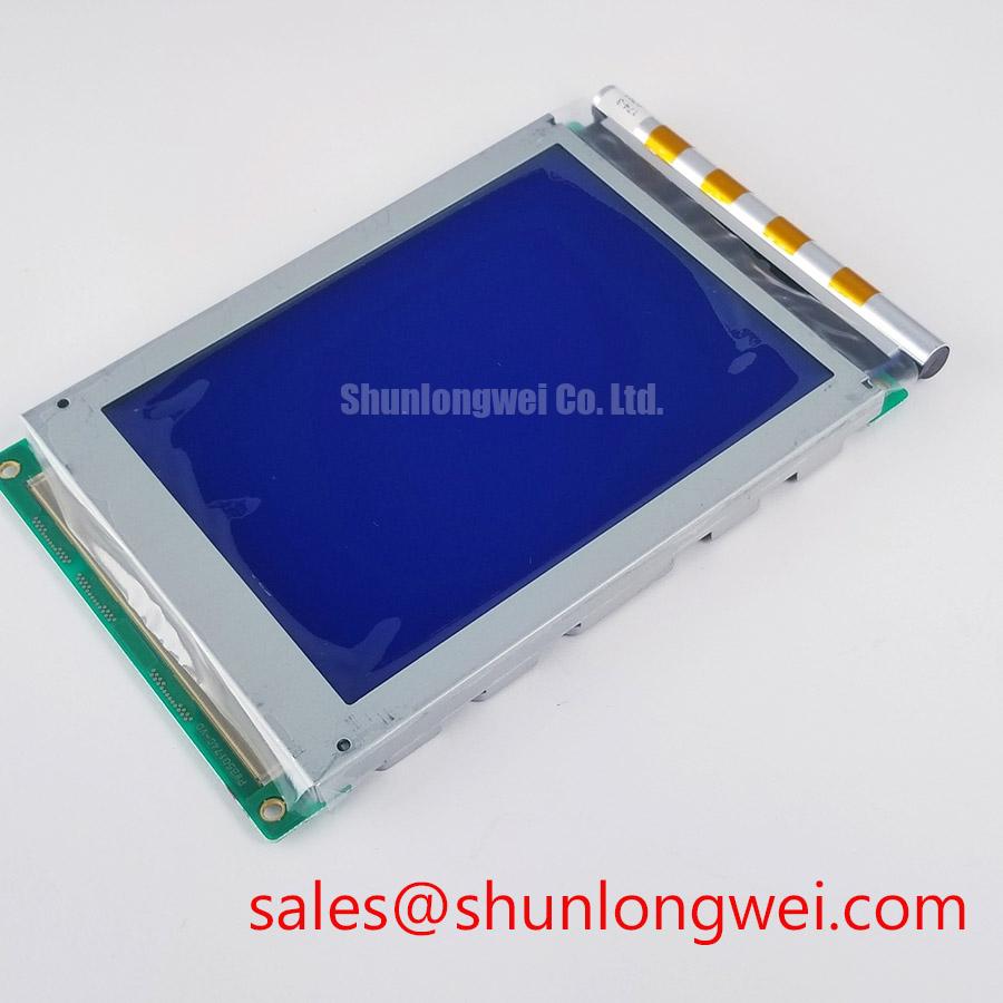
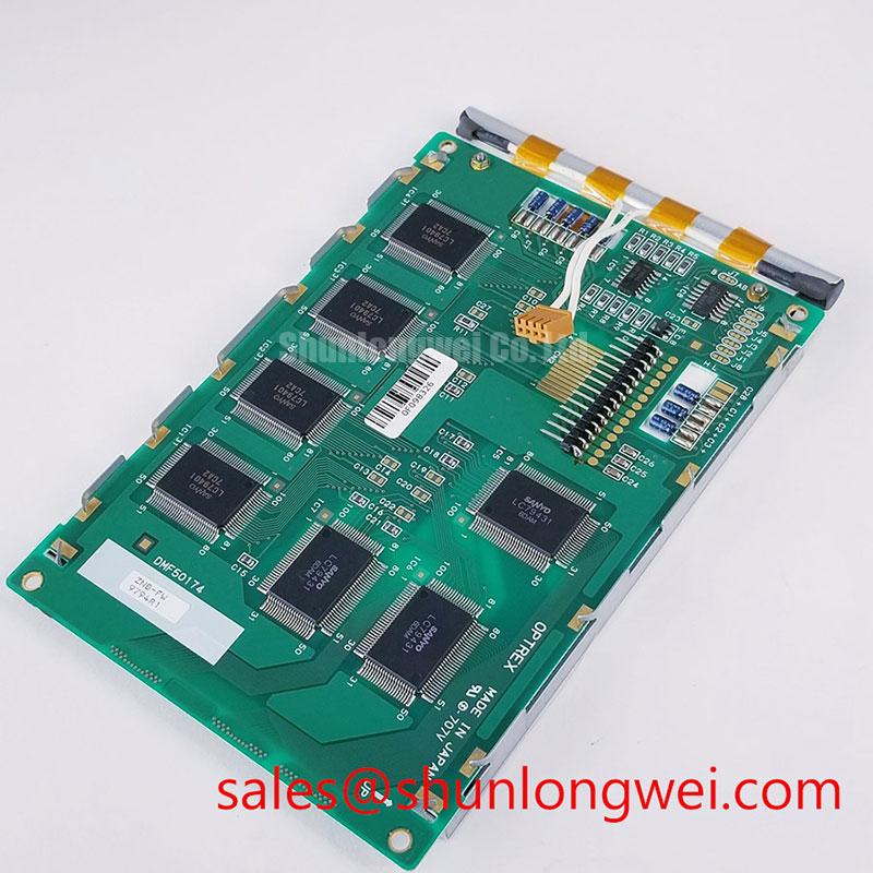



Content last revised on September 13, 2026
VESA vs. JEIDA Data Mapping Alignment & Even/Odd Channel Signal Integrity
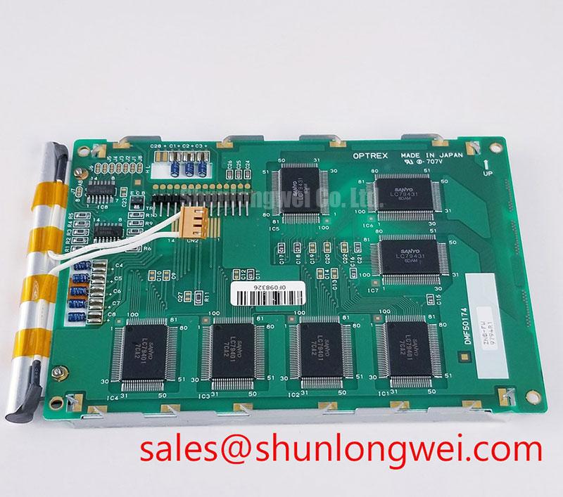
Split imagery, incorrect colors, repeated vertical regions, or unstable even and odd pixel areas can arise when a host display transmitter and panel receiver do not share the same data-mapping convention. VESA and JEIDA mappings are not interchangeable labels for an LCD module. They describe different serial data-bit assignments, so the system integrator should verify the mapping specified for the original DMF50174 installation rather than infer it from connector appearance or cable position.
The official structured product information identifies the DMF50174 as a TFT-LCD display module but does not establish a logic supply value, signal format, or timing sequence. Accordingly, the required supply voltage and interface configuration must be verified from the original panel documentation. A board that supplies an apparently plausible voltage can still be unsuitable if the panel expects another logic domain, a different enable order, or a different signaling method.
During bench evaluation, connect the known host cable only after its connector keying, contact count, latch geometry, and pin-one orientation have been checked. Inspect the receptacle with magnification where possible. A contact that is not fully seated can produce intermittent noise, missing color components, or a display that changes behavior when the enclosure is moved. These observations do not prove one specific defect; they identify a reason to compare the signal path with a known-good assembly using appropriate measurement equipment.
Power sequencing is also a system integration issue. The requested timing window of 0.5 ms < t1 < 10 ms must not be represented as an official DMF50174 rating without the original manufacturer timing table. It can instead serve as an engineering review item when examining the host board’s power-on waveform. The technician should capture logic supply, panel-enable, and video-activity events together, then compare their order and timing with the approved equipment documentation.
For differential video paths, controlled impedance routing is a Design Consideration, not a confirmed DMF50174 factory requirement in the supplied information. A nominal 100 Ω differential channel is commonly evaluated where the validated interface documentation calls for it. Cable substitution, connector rework, and unshielded adapters deserve particular attention because they can alter signal balance even when a static image appears acceptable.
Backlight dimming should also be observed as a host-system behavior. A PWM frequency in the 200 Hz to 1 kHz region and duty-cycle linearity may be evaluated where the original lighting controller uses PWM control, but these values are not stated official specifications of the DMF50174. Test natural text, grayscale windows, and dark interface pages at several brightness settings. Look for visible flicker, brightness steps, or sound originating from the host backlight circuit. The outcome should guide investigation of the controller and wiring rather than be assigned automatically to the display module.
💡 Bench Tip: Use ESD-safe handling and keep the flex cable square to the connector while closing its lock, because a skewed insertion can damage contacts or create intermittent image faults.
Eye-Diagram Voltage Margin & Differential Noise Floor Verification in High-Vibration Bays
A display that operates normally on an open bench can show pixel jitter, horizontal disturbance, or sporadic image loss after installation near motors, relays, switching power stages, or moving machinery. The useful diagnostic approach is to reproduce the equipment state in which the symptom occurs, inspect the cable route and grounding arrangement, and measure the signal at the receiver path against a known-good reference where available.
The supplied product information does not confirm the DMF50174 interface as LVDS. Therefore, LVDS terminology, eye-diagram limits, and FFC shielding arrangements must be treated as Design Considerations pending confirmation from the original panel documentation. If the documented host architecture uses LVDS, a technician can inspect whether differential conductors remain paired through adapters and whether the cable shield is terminated as intended by the equipment design.
In installations exposed to vibration, cable strain relief matters as much as electrical continuity. A cable can pass a stationary continuity check while changing contact pressure during movement. Inspect the cable’s bend path, fixation points, connector latch engagement, and clearance from sharp chassis edges. Where a flexible printed cable is present, avoid repeated bending at the same point near the connector tail. A visual fault that appears only after an enclosure door closes may indicate a mechanical interaction that should be observed directly during controlled reassembly.
Shield continuity around the cable entry can help reduce coupling from external noise sources when the host system’s grounding design calls for it. A 360-degree shield termination and common-mode ferrite are system choices that require validation in the complete assembly; they are not inherent features established for this DMF50174 module. Near high-voltage variable-frequency drives, the engineering objective is to reduce common-mode disturbance and preserve the differential signal margin while verifying actual peak behavior under the relevant operating condition.
For a documented differential link, 100 Ω ± 10% routing and a skew budget of 50 ps or less are often used as integration review criteria. They must not be treated as published DMF50174 electrical limits unless confirmed in the manufacturer documentation. The appropriate test is an eye-diagram or equivalent receiver-side signal-quality measurement using the actual cable, host transmitter, supply state, and nearby equipment activity. A narrowed eye or rising noise floor may indicate several possible issues, including cable routing, termination, ground reference behavior, transmitter degradation, or a connector problem.
The external environment should be assessed separately from the display module itself. Industrial display systems can involve insulation and high-voltage subsystems whose evaluation methods differ from display signal testing. For background on discharge phenomena in high-voltage equipment, see partial discharge detection. That reference does not establish any insulation, EMC, or reliability rating for the DMF50174.
Long-term test planning benefits from documented visual checks rather than unsupported life predictions. Track image stability, connector retention, brightness consistency, and display behavior during the host equipment’s actual duty cycle. Broader test methods and integration considerations are available through Industrial Display & HMI Solutions.
Chassis M3 Fastener Torque Evaluation (0.35–0.45 N·m) and Optical Mura Defects
Before fastening the DMF50174 into a host enclosure, place the inactive module on a clean, flat, ESD-safe support and inspect the visible area under low-angle illumination. This makes it easier to distinguish pre-existing optical nonuniformity from a pressure pattern introduced during installation. After fitting the panel, repeat the same white and dark-field inspection with the chassis in its final position.
The 0.35–0.45 N·m M3 torque range is a general installation reference from the requested integration context, not an official Kyocera / OPTREX DMF50174 mounting specification. The correct fastener size, torque, washer arrangement, bezel clearance, and tightening sequence must be taken from the module drawing and host mechanical design. If no approved drawing is available, engineers should avoid treating a generic torque value as authorization to mount the module.
Mechanical stress can present as localized mura, edge brightening, dark patches, or image changes that become more apparent on uniform gray and black patterns. Such effects may be associated with bezel pressure, uneven fastener loading, unsupported module corners, or enclosure distortion, but a single symptom should not be assigned to one cause without inspection. Loosen the mounting arrangement only under controlled conditions, observe whether the pattern changes, and compare the physical support points with the original assembly.
A cross-pattern tightening sequence is a Design Consideration for distributing chassis load where the documented mounting arrangement permits it. The objective is to prevent one corner from imposing excessive localized pressure before adjacent positions are seated. Check that the front bezel does not overlap the active viewing area, that no cable is trapped between the chassis and display, and that the rear surface has the clearance required by the original module documentation.
Clock jitter and data hold behavior also remain host-interface properties unless a validated DMF50174 timing specification is available. Temperature changes can alter cable behavior, connector contact resistance, and transmitter margins in the system. When image errors occur after thermal exposure, capture the relevant interface signals and compare them against an approved display path instead of relying only on a visual assessment. This separates optical pressure effects from signal-integrity concerns more effectively.
Static industrial HMI pages deserve their own inspection routine. Persistent toolbars, status icons, fixed measurement grids, and alarm windows can leave temporary image retention on some LCD assemblies depending on panel technology, drive conditions, and image content. The supplied data does not provide an image-retention rating or recovery behavior for the DMF50174. Where a host application displays fixed content for extended periods, the system owner should validate its screen-management method with the original panel documentation and visual testing rather than claim a predictable service duration.
Temperature Evaluation (−30°C to +85°C) & Sub-Zero Liquid Crystal Viscosity
The stated −30°C to +85°C range must not be presented as an official operating or storage rating for the DMF50174 because that range is not included in the supplied verified factory specification table. It is an environmental evaluation topic only. The actual allowable operating, storage, humidity, shock, vibration, and thermal-cycle limits must be confirmed from the original Kyocera / OPTREX documentation before the module is approved for an exposed industrial enclosure.
At low temperature, liquid-crystal response can slow, and gray transitions may appear less immediate than at room conditions. The degree of change depends on the panel construction, driving conditions, temperature history, and host electronics. A technician should allow the assembly to stabilize at the relevant test temperature, display moving grayscale and text patterns, and record any ghosting, delayed transitions, or uneven response. Such observations should be evaluated against the approved equipment behavior rather than used to infer an unsupported panel specification.
Thermal cycling also places stress on cable routing, connector latches, chassis interfaces, adhesives, and perimeter seals. The supplied information does not provide sealant construction, material composition, or thermal-cycle endurance for this module, so no claims should be made about its internal materials or cycle life. External inspection remains useful: look for perimeter separation, changes in bezel pressure, cable stiffening, or loss of connector retention after controlled environmental exposure.
The requested optical condition of more than 500:1 contrast at 50,000 lux and an anti-glare surface must likewise be verified from the original manufacturer documentation before being associated with the DMF50174. Sunlight readability depends on display contrast, surface treatment, optical stack, enclosure window reflections, viewing angle, and ambient illumination. For equipment intended for bright-area use, test the completed enclosure in representative light and evaluate whether reflections obscure critical text, symbols, or grayscale features.
Potential evaluation for high-precision surgical navigation or ultrasound diagnostic display equipment should remain subject to the equipment manufacturer’s regulatory, optical, electrical-safety, cleaning, and qualification requirements. The DMF50174 is identified here only as a Kyocera / OPTREX industrial TFT-LCD display module with official factory specification status verified. Its suitability for any regulated or safety-relevant assembly must be determined through the complete system documentation and validation process.