

Content last revised on September 10, 2026
Industrial Bezel Mechanical Envelope Tolerances and Mounting Screw Torque Control
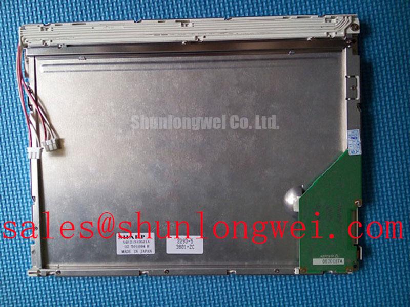
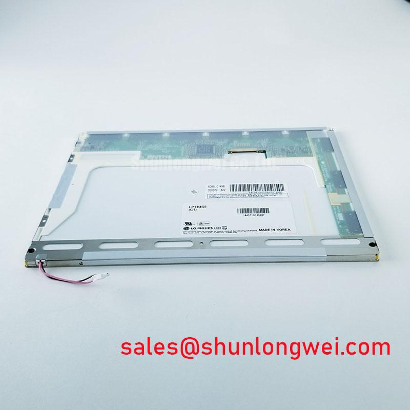
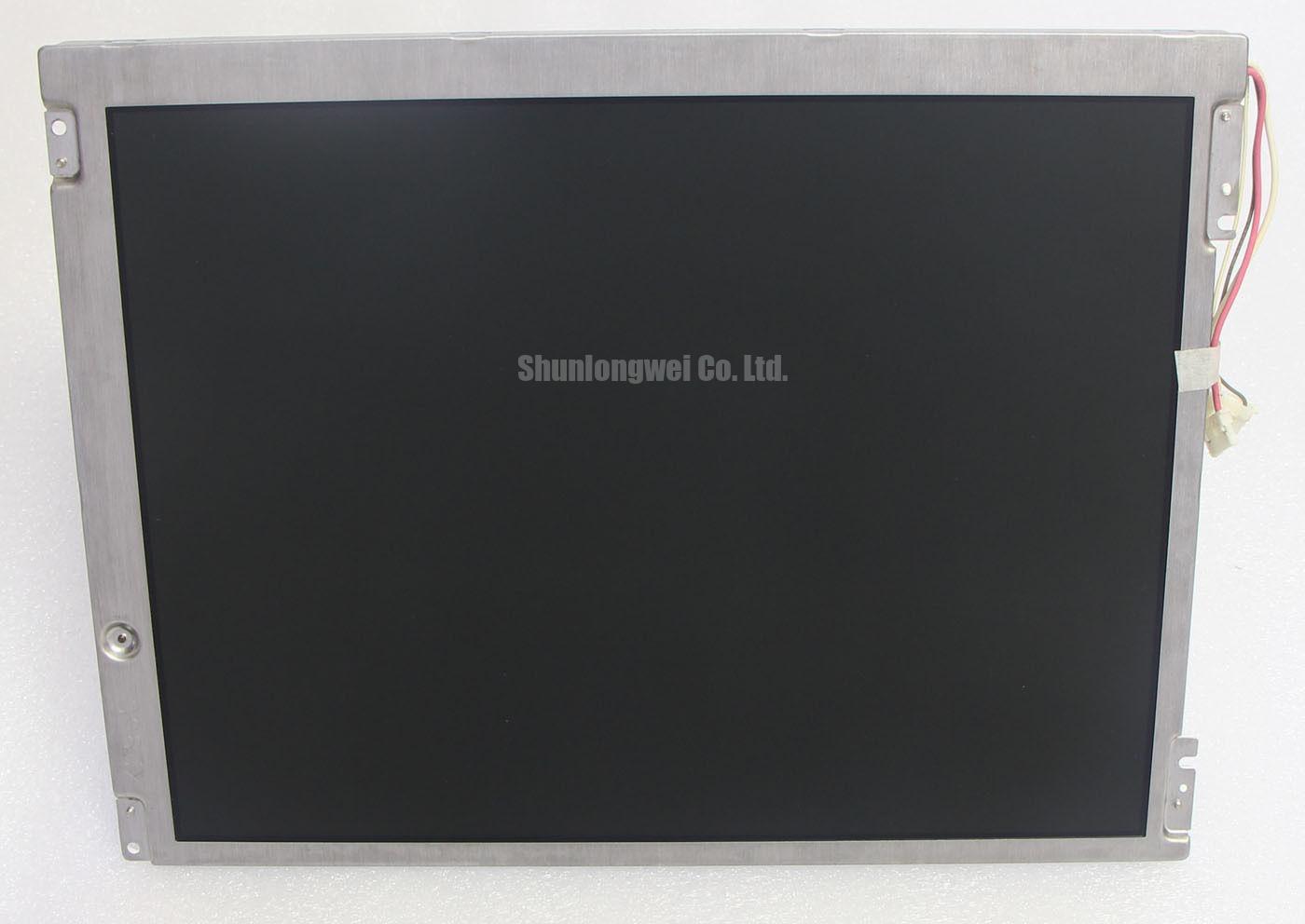
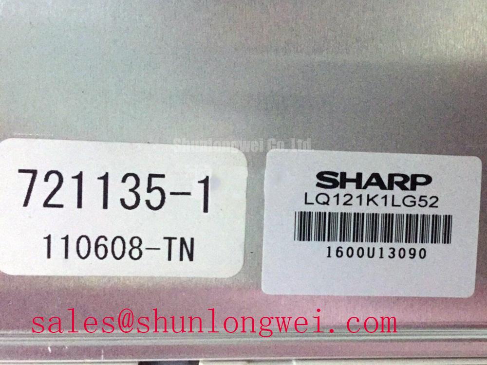
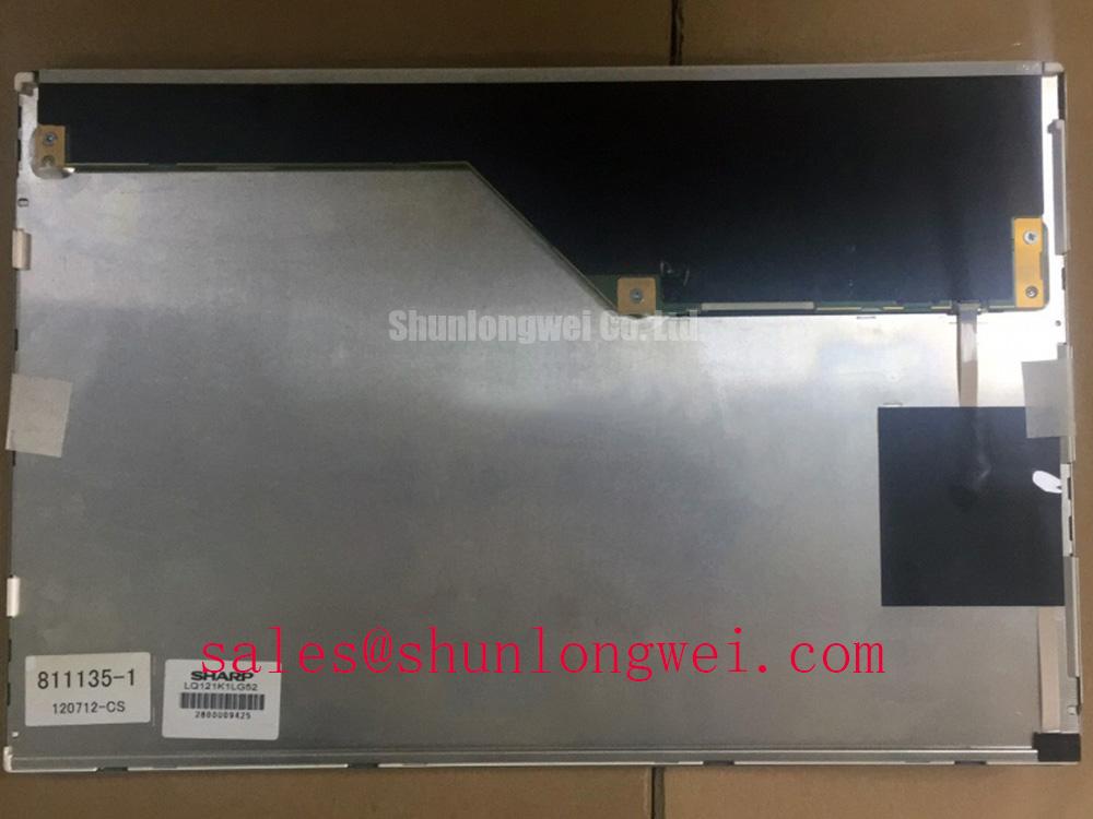
Begin the incoming inspection by confirming that the label identifies LQ121S1LG52, then examine the TFT-LCD display module perimeter, connector area, and exposed mounting surfaces under controlled lighting before it enters a replacement workflow. The available factory-verified identification defines this Sharp unit as an Industrial Grade LCD/HMI Panel in a TFT-LCD Display Module format. Electrical input ratings, interface assignment, optical values, environmental limits, and mechanical drawing dimensions should be verified against the documentation for the original panel assembly before energizing or substituting the module.
For a failed industrial display assembly, record the host equipment model, existing panel part number, connector orientation, bezel opening, mounting-point arrangement, and the display controller’s observed signal format. A display can fit a front cutout yet remain electrically unsuitable because of different pin assignments, power sequencing, timing, or interface mapping. These checks are particularly important where the original unit is installed in a diagnostic display terminal, industrial operator station, machine-vision console, or another enclosure where stable image presentation is part of the service decision.
The LQ121S1LG52 should be treated as a panel assembly rather than a structural chassis member. Before fixing it into a bezel, inspect the enclosure opening for burrs, warped retaining rails, trapped gasket fragments, and uneven contact points. Local pressure applied through a bezel edge or mounting tab can create visible nonuniformity, especially when a dark image is displayed. Such symptoms should be evaluated with the panel relaxed and then mounted, rather than being assigned to a single cause without comparison.
Design Consideration: use the original Sharp mechanical drawing and host-equipment mounting arrangement to determine the acceptable bezel clearance, screw type, washer stack, and fastening sequence. If an M3 mounting scheme is used by the existing assembly, tighten progressively in a cross pattern using a low, controlled torque appropriate to the panel drawing, frame material, and mechanical retention method. The responsible technician should validate the final torque against the panel documentation and the equipment manufacturer’s assembly requirements.
⚠️ Maintenance Note: Tighten the display progressively in a cross pattern and stop if the bezel begins to transfer point load into the active viewing area.
Do not use the front polarizer surface as a seating reference. Support the module only through its documented frame and mounting features. When a foam gasket or dust seal is part of the front enclosure, inspect for compression set, tears, displaced adhesive, and discontinuities at corners. A seal that is too thin can leave the display mechanically unsupported; a seal that is too thick can place continuous bending force on the panel once the bezel is secured. Either condition requires enclosure correction, not repeated tightening.
For repair planning, compatibility cannot be established from screen size or a broadly similar appearance. The LMS700KF01-001 can be reviewed as a separate display-module reference during material evaluation, but its mechanical outline, signal interface, electrical requirements, and optical behavior must be checked independently against the original assembly. A substitution decision should remain with the system engineer after drawing and interface verification.
Where a display controller uses high-speed differential signaling, cable routing and connector seating affect image stability as much as the panel’s physical installation. Design Consideration: maintain the impedance control and pair matching specified by the host controller and display documentation, while routing away from servo motor leads, inverter output cabling, contactors, and switching power loops. A distorted image, intermittent blanking, or unstable pixel regions may indicate several possible issues, including a disturbed cable path, poor connector retention, supply instability, controller failure, or panel-interface mismatch. Compare the suspect path with a known-good configuration using appropriate measurement equipment before replacing parts.
Thermal Cycling, Perimeter Sealing, and Condensation-Aware Service Practice
Temperature changes affect the complete display assembly: the liquid-crystal optical behavior, front-surface condensation risk, cable flexibility, enclosure gasket condition, and the mechanical relationship between the bezel and panel frame. The available factory identification does not establish a numerical operating-temperature range for LQ121S1LG52; therefore, equipment technicians should obtain the relevant Sharp documentation and the host system environmental specification before approving operation in cold storage areas, heated cabinets, outdoor enclosures, or washdown-adjacent locations.
At low ambient temperature, liquid-crystal response can appear slower than it does in a stabilized room environment. This observation should not be used as a pass or fail criterion without the original timing and environmental limits. If the panel is being assessed after cold exposure, allow the complete enclosure to reach a stable temperature before concluding that ghosting, delayed grayscale transitions, or uneven appearance is a permanent defect. Rapid re-energization after a major temperature transition can obscure the source of an observed display problem.
Engineering Recommendation: manage condensation through enclosure design, ventilation control, and service handling rather than by applying direct heat to the panel surface. If a cabinet has been moved from a cold area into a warm and humid work zone, inspect the connector, cable, bezel seam, and surrounding electronics for moisture before power is restored. The panel should be dry, mechanically secure, and connected only after the equipment’s established maintenance procedure permits restart.
Perimeter seals deserve attention because their condition influences both dust ingress resistance and the uniform loading of the front assembly. Look for sections that have lifted from the bezel, hardened areas that no longer follow the enclosure contour, or adhesive residue that prevents flat seating. Replace sealing materials only with materials appropriate to the equipment enclosure and service environment. No claim should be made that a replacement gasket restores a particular ingress-protection classification unless the complete installed system has been evaluated to the relevant requirement.
For long-running display assemblies, periodic checks should include cabinet air paths, filter condition, fan operation where fitted, and the condition of the front seal. These are maintenance controls for the host equipment, not factory performance claims for the display module. A practical review of industrial TFT display behavior, interface selection, and commonly misunderstood panel characteristics is available in The Ultimate Guide to Industrial TFT LCD Technology.
Potential use in a surgical-navigation or ultrasound diagnostic display terminal requires additional system-level review. Cleanability, enclosure sealing, display calibration, electrical safety, image-processing behavior, and the regulatory status of the complete medical equipment are responsibilities of the equipment manufacturer or qualified system integrator. The LQ121S1LG52 identification alone does not establish suitability for a regulated medical function.
Controlled Differential-Signal Routing and Power-Up Verification
Before connecting a replacement panel, trace the original harness from the display controller to the module connector and verify that it has not been pinched by the bezel, twisted around a hinge path, or pulled under tension. The factory information provided for LQ121S1LG52 does not confirm the logic supply voltage, connector pinout, signaling protocol, or data mapping. The system integrator should verify the required supply voltage from the original panel documentation and should not infer it from another Sharp panel or a visually similar connector.
Power sequencing is a system-dependent requirement. A display can show no image, an unstable image, or repeated startup behavior when a controller applies signals before the expected supply state is established, but those symptoms are not exclusive to sequencing. Verify the host power rails, enable controls, connector contact integrity, cable continuity, and controller output against the original system documentation. Oscilloscope comparison to a known-good signal path can help distinguish timing-related behavior from cable, controller, or panel faults.
Design Consideration: where the host interface uses differential pairs, preserve the controlled impedance and pair-to-pair timing requirements established by the controller and cable design. Avoid unplanned cable extensions, improvised splices, or sharply folded flex sections near the connector. High-frequency noise from variable-speed drives, servo amplifiers, relay coils, and switching converters can couple into poorly routed display wiring. The correct response is to inspect shielding continuity, return paths, grounding architecture, cable separation, and controller design limits rather than to assign a fixed interference tolerance to the panel.
JEIDA and VESA mappings are not interchangeable assumptions. If the existing controller documentation identifies one mapping, maintain that mapping through the full signal chain. If the documentation is unavailable, capture the original configuration before removal where possible, then validate the replacement assembly using controlled bench tests. Split imagery, incorrect color ordering, unstable image regions, or a blank raster can arise from several interface-related conditions. The panel should not be operated beyond verified electrical conditions while troubleshooting.
A separate display-module reference such as LQ9D03B may be relevant when cataloging a broader display-system repair requirement, but it must not be assumed to provide a compatible electrical, optical, or mechanical replacement path. Review each module against the host system’s documented interface and retention requirements.
Surface Readability, Cleaning Boundaries, and Touch-Overlay Integration
Assess front-surface readability with the display installed in its intended bezel and lighting geometry. Reflections can originate from the panel surface, an added protective window, a touch overlay, the bezel angle, or direct ambient illumination. The official factory information supplied for LQ121S1LG52 does not confirm an anti-glare treatment, anti-reflective treatment, contrast ratio, viewing-angle specification, or sunlight-readability rating. These properties must be verified from the original panel documentation rather than inferred from the product category.
Design Consideration: an anti-glare surface can reduce the definition of direct reflections, while an anti-reflective optical stack aims to reduce reflected light through a different mechanism. Their visual results depend on the complete front assembly, including any cover lens, adhesive layer, touch sensor, and enclosure geometry. Adding a film or cover lens can change haze, reflections, color appearance, touch sensitivity, thermal behavior, and mechanical loading. System engineers should evaluate those changes with the actual display controller, enclosure, and intended lighting condition.
For service cleaning, remove loose dust using a method approved for the equipment, then use only cleaning materials authorized by the panel or equipment documentation. Avoid abrasive wipes, excessive liquid, and uncontrolled solvent exposure around edges and connectors. If the terminal includes a touch overlay, identify whether it is part of the original assembly or an independent layer before disassembly. Capacitive and resistive touch technologies have different mechanical structures and controller requirements; neither should be assumed for LQ121S1LG52 without documentation.
Glove operation, wet-surface response, and touch sensitivity are attributes of the complete touch solution, not of the TFT-LCD module identity alone. When a display terminal is expected to be operated through gloves or in environments where moisture is possible, verify the original touch-controller settings, overlay sealing, front-window stack, and operator-interface requirements at system level. A visual display replacement should not be expected to correct unrelated touch faults.
In high ambient-light areas, practical assessment should use the actual enclosure angle, work distance, task lighting, and displayed content. Text legibility, grayscale discrimination, and reflection control can vary significantly between a white service screen and the live machine interface. Record the observed behavior before and after installation, retaining photos and controller settings with the maintenance record. This approach supports a traceable repair decision without assigning unsupported optical or environmental ratings to the Sharp LQ121S1LG52 TFT-LCD display module.