

Content last revised on September 10, 2026
Shielded FFC/FPC Flat Flexible Cable Grounding across 360-Degree Connector Shells
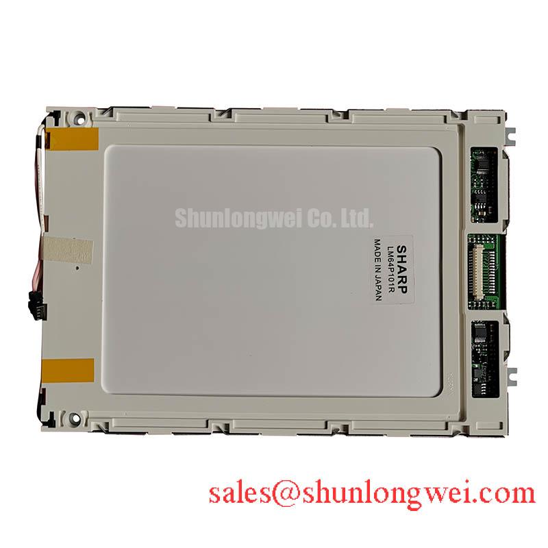
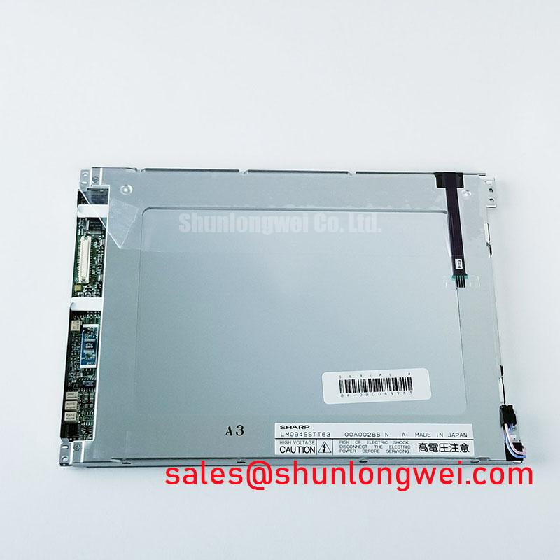
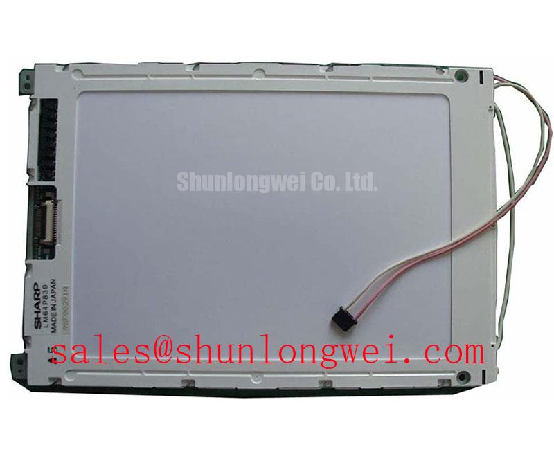
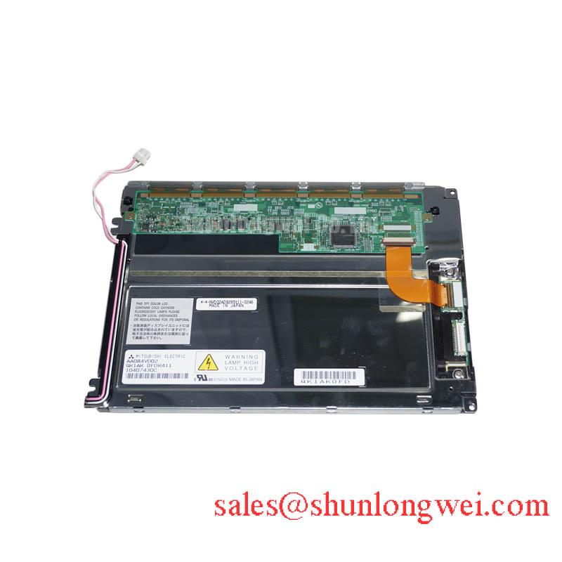
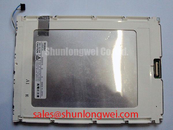
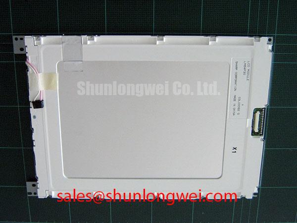
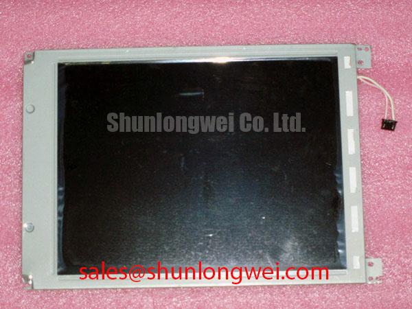
LM64P30 is a Sharp industrial grade LCD/HMI panel supplied as a TFT-LCD display module. The available factory-verified information identifies the manufacturer, product category, package form, and official specification status, but it does not confirm a complete pinout, active display area, resolution, viewing angle, luminance, touch function, backlight type, or electrical timing table. Those values should be checked against the original Sharp documentation or the equipment service manual before installation.
| Model | LM64P30 |
| Manufacturer | Sharp |
| Product category | Industrial Grade LCD/HMI Panel |
| Package or housing | TFT-LCD Display Module |
| Specification status | Limited Factory Information Verified |
For a hazardous petrochemical Zone 2 explosion-proof operator station or a field monitoring terminal, the display module remains one part of a larger certified assembly. The panel itself should not be treated as independently holding the enclosure, ignition protection, EMC, or system safety certification of the completed operator station. Mechanical sealing, cable entry, bonding, thermal management, and the certification file for the host equipment remain system-level responsibilities.
Begin the signal inspection with the cable and connector rather than assuming that a blank or unstable image is caused by the LCD glass. Confirm the connector orientation, contact count, cable fold direction, and locking mechanism against the original assembly. The available factory information for LM64P30 does not publish a confirmed LVDS or TTL pin assignment, so the integrator should not apply a generic display cable without checking the source panel documentation.
In equipment positioned near variable-frequency motor drives, servo amplifiers, or switching power converters, shield continuity can affect the visible image even when the logic supply appears correct. A shielded FFC or FPC should be bonded according to the host equipment’s EMC architecture. A 360-degree termination can reduce the exposed path for common-mode currents when the connector shell, cable shield, chassis bonding point, and enclosure are designed as one controlled return structure. The correct bonding method depends on the panel connector construction and the safety requirements of the complete operator station.
Common-mode ferrite suppression is a design consideration, not an LM64P30 factory parameter. If a ferrite is evaluated, its impedance profile should be checked across the actual interference spectrum, along with its effect on the display cable’s signal margin. Excessive filtering, poor shield pigtails, or a long unreferenced cable section can create a different signal-integrity problem. Engineers should verify the known-good signal path with an oscilloscope or suitable high-speed measurement fixture while observing pixel-clock stability, data transitions, and the appearance of horizontal noise bands.
For any differential display interface, controlled impedance and pair symmetry are useful design principles. A commonly used LVDS routing target is 100 Ω differential impedance with tightly controlled pair skew, but these are system design considerations and are not confirmed factory specifications for LM64P30. The applicable impedance, termination, data mapping, and clock relationship must come from the original panel interface documentation. Keep the cable away from high-current switching loops and verify the complete assembly under the actual motor-drive operating state.
💡 Pro Tip: Disconnect power before inserting or removing the display cable, because live insertion can damage the panel interface or the host controller.
Viewing Direction, Grayscale Inversion & Panel Optical Alignment
The optical construction of LM64P30 should be identified from the original Sharp specification before a replacement bezel or viewing window is designed. The supplied factory data does not confirm whether this model uses TN, IPS, MVA, or another LCD mode, and it does not provide a verified viewing-angle table. Do not transfer the viewing-cone assumptions of an IPS or MVA panel to this model without documentation.
When a panel uses a TN architecture, grayscale inversion can become visible when the operator views the screen outside the intended vertical direction. A practical evaluation places the installed panel at the actual operator position and checks neutral gray ramps, small text, alarm symbols, and trend graphics from the expected standing and seated angles. If gray levels change strongly with viewing direction, the enclosure angle, display mounting orientation, and screen layout may need review. This is an integration observation rather than a declared LM64P30 performance limit.
Anti-glare treatment should also be evaluated in the finished enclosure. Surface etching, cover glass, protective film, and the angle of overhead lighting can change perceived contrast. In a petrochemical control station, the display window may be exposed to strong ambient illumination, reflections from stainless steel surfaces, and contamination from dust or process residue. The system integrator should assess readability with the final window, gasket, bezel, and lighting arrangement rather than relying on a bare-panel inspection.
Touch capability is not confirmed in the available factory parameters. If the host assembly requires resistive or capacitive touch input, verify the touch layer, controller interface, active area, cover construction, and calibration method separately. Gloved operation and operation with moisture on the surface are application tests, not assumptions that can be assigned to LM64P30. A replacement display without the required touch stack may fit mechanically while remaining unsuitable for the operator interface.
Backlight endurance claims also require source documentation. The available product data does not verify an LED backlight half-life, a CCFL operating life, an MTBF figure, or a specified luminance decay curve. Constant-current operation, enclosure temperature, optical obstruction, and local heat concentration can all influence brightness stability. Engineers should measure luminance and temperature at the assembled display position if long-duration operation is part of the acceptance plan.
Display Interface Synchronization & Logic Power Rail Verification
Do not assume that LM64P30 accepts a 24-bit TTL RGB bus merely because that interface is common among industrial LCD modules. The available factory-verified data does not publish the model’s logic supply voltage, signal standard, pinout, pixel format, polarity, power-on timing, or JEIDA/VESA mapping. The system integrator should verify the required supply voltage from the original panel documentation and confirm every control signal before connecting a controller board.
If the source equipment uses TTL RGB, the engineer should compare the red, green, and blue bit order, pixel clock edge, horizontal and vertical synchronization, data-enable behavior, and display enable sequence with the original design. A JEIDA/VESA mismatch can produce incorrect colors or split-screen artifacts without indicating a defect in the LCD module. If the source equipment uses LVDS instead, the serializer configuration and differential pair order must be matched to the panel specification rather than inferred from connector appearance.
Power sequencing is another system-controlled item. Confirm the order and timing relationship between logic power, display enable, reset, pixel clock, and backlight control from the source documentation. A controller that applies an unverified voltage or drives data while the panel is outside its permitted startup state may cause intermittent operation or long-term interface stress. The exact rise-time limits and timing windows supplied in the original specification should be checked on the assembled controller with the display connected.
T-CON behavior, grayscale voltage generation, and gamma correction should be evaluated at the panel interface level. A distorted gray ramp, missing shades, or uneven color response can arise from incorrect timing, gamma settings, signal mapping, supply quality, or optical conditions. Replaceable controller settings should be compared with a known-good configuration before altering the panel hardware. The available LM64P30 information does not provide factory gamma-voltage points or T-CON register values, so those values must not be invented for a repair procedure.
Routing is best treated as a complete signal-integrity problem. Maintain a continuous reference path, avoid unnecessary stubs, control return-current transitions, and verify the clock and data margins at the panel connector. If a system specification calls for a particular characteristic impedance or skew limit, validate that requirement against the controller and cable combination. A direct measurement is preferable to diagnosing image breakup from appearance alone.
The LM64P10 can be reviewed as a separate same-class replacement candidate during sourcing analysis, but compatibility should be established from its own interface, optical, mechanical, and timing specifications. Similar naming or a similar panel category does not establish drop-in interchangeability.
Optical Luminance Degradation Curve & Backlight Modernization Retrofit Pathways
Before planning a backlight retrofit, identify the original LM64P30 backlight technology and its electrical interface. The supplied factory parameters do not confirm CCFL, LED, lamp voltage, LED current, dimming method, connector assignment, optical stack, or brightness rating. An LED conversion therefore requires a documented compatibility review rather than a generic constant-current driver.
A CCFL assembly and an LED assembly differ in ignition behavior, current regulation, electromagnetic emissions, thermal distribution, dimming control, and mechanical placement. If the original equipment contains a high-voltage lamp inverter, the service engineer should follow the host manufacturer’s discharge and isolation procedure. If an LED driver is proposed, verify its current regulation, enable logic, dimming input, startup behavior, fault response, and conducted and radiated emissions within the complete enclosure.
Claims such as a 50,000-hour half-brightness life, a 1,000:1 PWM range, or a particular PWM frequency are not confirmed factory specifications for LM64P30 in the supplied data. They should not be presented as guaranteed performance for this model. The retrofit designer should obtain the actual backlight datasheet and test luminance uniformity, flicker perception, acoustic behavior, local temperature, and image readability with the final bezel and cover window installed.
Local hot spots deserve attention in enclosed operator stations. The backlight, driver, sealing layer, and metal mounting frame can create temperature gradients that are not visible during a short bench test. Measure the assembled unit at the brightest intended operating condition and inspect areas near the driver, cable entry, and optical edge. Thermal conclusions should be based on the panel and enclosure documentation together with measured operating conditions.
For a repair procurement decision, retain the original connector and mounting references, record the host controller configuration, and compare the replacement against the equipment’s approved interface documentation. The The Ultimate Guide to Industrial TFT-LCD Technology provides broader background for evaluating panel interfaces, optical behavior, and industrial integration criteria. LM64P30 remains identified here as a Sharp TFT-LCD display module with limited factory information verified, while unconfirmed electrical and optical values require verification before field installation.