
Scan Part Number

Tap the focus box or CAPTURE to scan the part number.

Pinch screen or tap 1.4x button to zoom.

Recognizing Part Number...

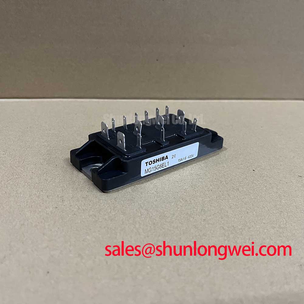
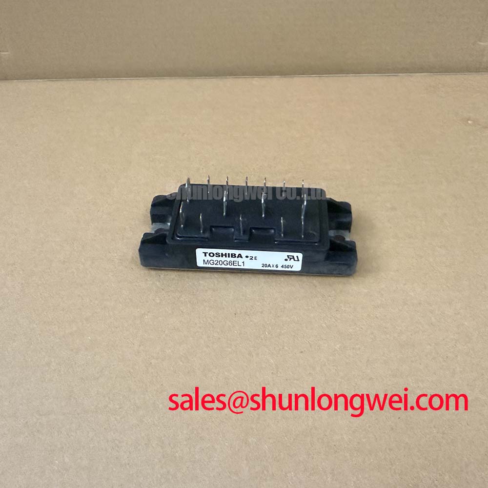
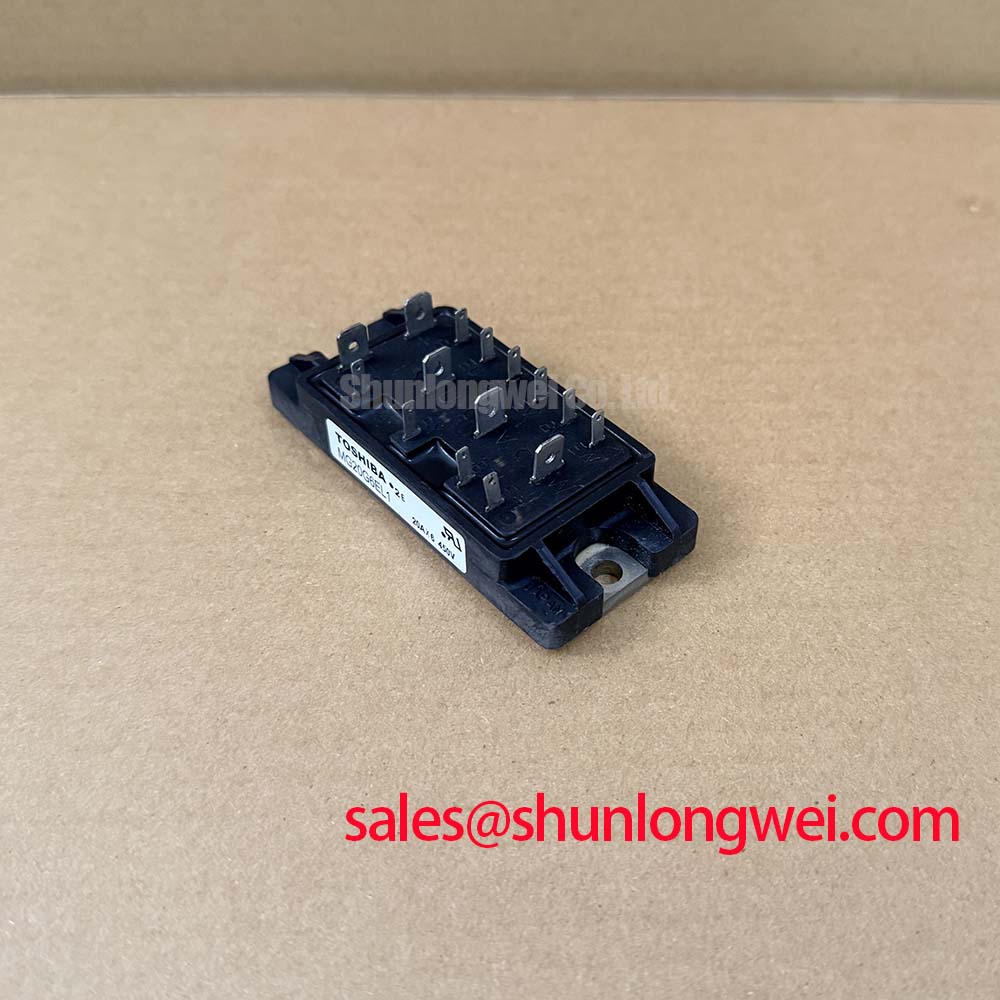
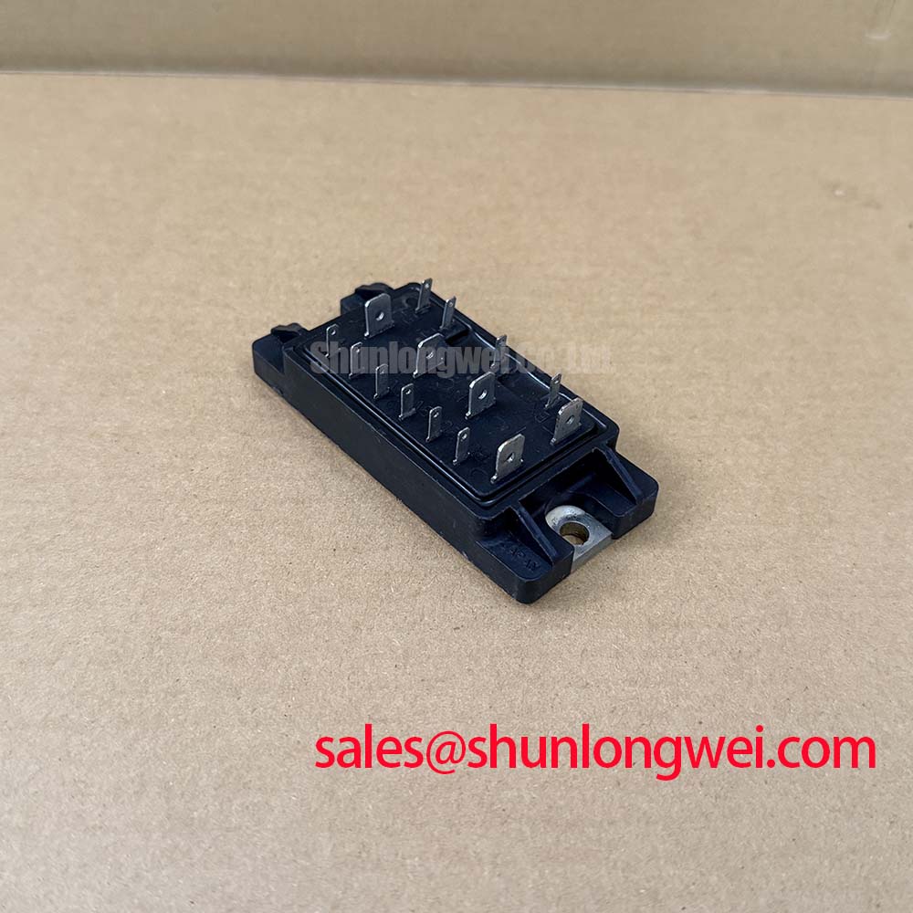
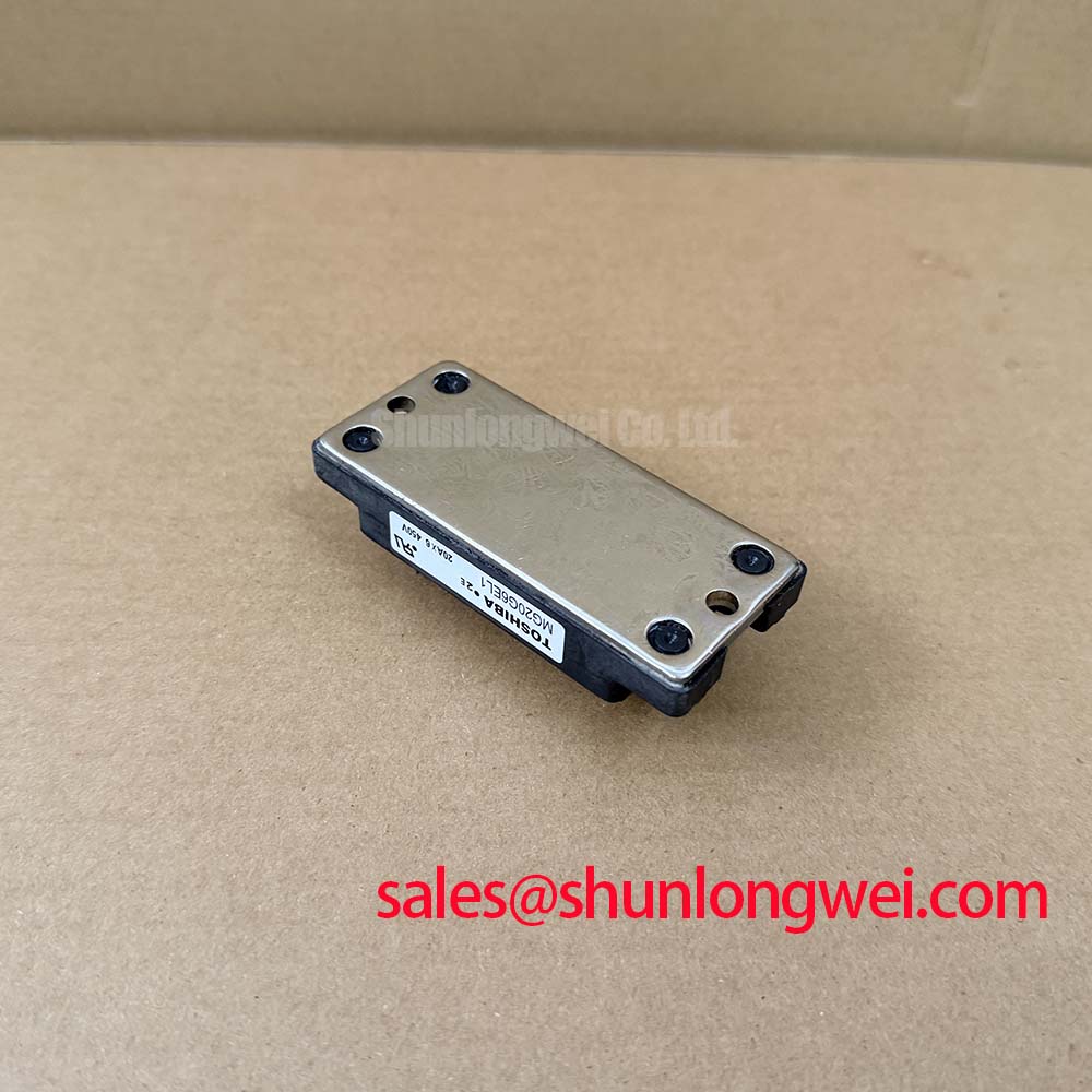
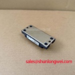
MG20G6EL1 Toshiba 450V 20A Power Transistor Module

MG20G6EL1 IGBT Module In-stock / Toshiba: 450V 20A 125W VCE(sat) 2.0V. 90-day warranty, Wind Pitch & Industrial Drives. Global fast shipping. Get quote.

· Categories: IGBT
· Manufacturer: Toshiba
· Price: US$ 20 In-Stock Offer
· Date Code: Please Verify on Quote
. Available Qty: 272
MOQ: 1 PC
Express Shipping
90-Day Warranty
1-2 Days Lead Time
100% Tested
Whatsapp: 0086 189 2465 1869

Content last revised on September 10, 2026

Toshiba MG20G6EL1 Technical Analysis and Field Reliability Assessment

The Toshiba MG20G6EL1 is an integrated power switching module designed for medium-power switching, industrial motor control, and converter circuits. As plant maintenance and operations leads, our primary operational focus is maximizing Mean Time Between Failures (MTBF) and eliminating unscheduled downtime in severe industrial environments. Operating power electronics in harsh conditions—such as high-altitude wind turbine pitch and yaw converter cabinets located above 3000 meters—presents distinct physical challenges: reduced atmospheric pressure, diminished convective cooling efficiency, accelerated thermal cycling, and high common-mode electrical noise.

To establish baseline operating envelopes for maintenance validation and component replacement, the factory specifications for the MG20G6EL1 are structured below:

Parameter Official Datasheet Specification Engineering Test Condition
Collector-Emitter Voltage (VCEO) 450V Base Open, Rated Blocking Voltage
Collector Current (IC) 20A Continuous DC Operation
DC Current Gain (hFE) 100 (Min) VCE = 5V, IC = 20A
Collector-Emitter Saturation Voltage (VCE(sat)) 2.0V (Max) IC = 20A, IB = 0.2A
Collector Power Dissipation (PC) 125W Tcase = 25°C
Maximum Junction Temperature (Tj) 150°C Continuous Operating Limit

⚠️ Maintenance Note: In high-altitude installations (>3000m), the thermal resistance between the module baseplate and ambient air increases significantly due to lower air density. Routine thermal imaging audits should confirm that baseplate interface temperatures do not exceed 85°C under maximum steady-state torque demands, preventing localized silicon die hotspots from approaching the 150°C rated junction threshold.

High dv/dt Cross-Conduction Shoot-Through Mitigation via Dedicated Miller Clamps

In high-altitude wind turbine pitch actuator drives, fast-switching inductive loads induce steep voltage transients (dv/dt) across the collector-emitter junctions of the non-conducting power stages. When the complementary upper or lower transistor in a bridge arm switches on rapidly, the high dv/dt transient charges the parasitic collector-base (or collector-gate) capacitance (Cob / Cgc). This dynamic displacement current follows the physical relationship:

idisplacement = Cgc × (dv/dt)

If this induced displacement current flows through the intrinsic base/gate turn-off impedance, it develops a positive voltage drop across the input terminals. When this transient voltage exceeds the conduction threshold, parasitic turn-on occurs, creating a direct line-to-line shoot-through path across the DC bus. For the Toshiba MG20G6EL1, operating with a maximum collector rating of 20A and a saturation voltage VCE(sat) of 2.0V, unmitigated cross-conduction causes severe transient overcurrent spikes, escalating junction self-heating and degrading internal bond wires.

To eliminate cross-conduction risks without adding excessive switching losses through inflated series gate resistors, field retrofits and driver stage designs utilize two primary circuit countermeasures:

  • Active Miller Clamp Circuitry: An auxiliary low-impedance path is established directly at the control terminal. When the drive logic commands the module off, the Miller clamp transistor monitors the terminal voltage. Once the voltage falls below a threshold (typically ~1.5V to 2.0V), the clamp engages, shorting the gate/base directly to the negative emitter reference through an impedance below 1.0 Ω. This shunts dv/dt displacement currents away from the internal drive logic.
  • Negative Turn-Off Bias: Applying a dedicated negative off-state bias (-5V to -9V) expands the dynamic noise margin. The induced Miller spike is held safely below the device conduction threshold, preventing partial channel conduction during rapid transitions.

For auxiliary solid-state relay interlocks and control isolation across the pitch control architecture, standard galvanic isolation rules apply, as outlined in technical discussions of Solid-State Relay (SSR) Working Principles.

During pitch drive fault analysis, desaturation detection circuits monitor the on-state voltage across the MG20G6EL1. If the collector-emitter voltage fails to collapse below 2.0V during full conduction commands—indicating a mechanical stall or locked pitch gear—the driver triggers a Soft Turn-Off (STO) routine. Abruptly interrupting short-circuit current causes catastrophic Lstray × (di/dt) overvoltage spikes. Soft turn-off discharges the control terminal over an extended 2.0μs to 5.0μs window, keeping the device strictly within its Short-Circuit Safe Operating Area (SCSOA).

Derating Guidelines and Mismatched Parameter Compensation in Parallel Operation

Deploying the MG20G6EL1 in harsh turbine nacelles at altitudes exceeding 3000 meters requires rigorous environmental derating. Atmospheric thinning reduces both convective cooling efficacy and the dielectric breakdown strength of air (Paschen's Law). Consequently, external creepage and clearance distances must be scaled up by an altitude correction factor (typically 1.25× to 1.45× per IEC 60664-1), and electrical operating limits must be adjusted accordingly:

Operating Domain Sea-Level Reference Derated High-Altitude Target (>3000m) Engineering Rationale
DC Bus Working Voltage 300V - 350V 250V - 280V Prevents cosmic ray-induced single event burnout (SEB) and accounts for reduced dielectric insulation.
Continuous Output Current 20A 13A - 15A Compensates for a 20% to 30% reduction in heatsink convective heat transfer in thin mountain atmospheres.
Continuous Power Dissipation 125W (at 25°C) 65W - 75W (at 70°C ambient) Guarantees junction temperature Tj remains below 125°C to avoid accelerated thermal fatigue.

When wind pitch actuators demand higher drive currents than a single MG20G6EL1 can support, modules may be operated in parallel configurations. Effective static current sharing depends heavily on the collector-emitter saturation voltage VCE(sat) and the DC current gain hFE (specified at a minimum of 100 at IC = 20A). If one transistor possesses a lower saturation voltage or higher gain, it will draw a disproportionate share of the total load current.

In high-power line-synchronized pitch converter stages, front-end rectification provides regulated intermediate DC bus rails using phase-controlled thyristor/diode bridges, where average DC voltage is governed by:

Vdc = Vdo × cos(α)

Maintaining stable control requires tight regulation of the firing angle (α) and input line filtering to prevent harmonic distortion from interfering with the switching stages. For systems requiring upgraded power ratings during overhaul or redesign, engineers frequently review pin-compatible or higher-capacity options such as the MG30V1BS41 to handle expanded continuous current demands.

To ensure balanced load distribution in paralleled arrays:

  • Static Matching: Group modules from identical manufacturing lots with VCE(sat) values matched within ±50mV at rated current.
  • Dynamic Symmetrical Routing: Design identical PCB track lengths and equal parasitic loop inductances for every paralleled branch. Unequal gate/base circuit trace lengths introduce switching delays, forcing the faster module to carry the entire inductive load during switching intervals.
  • PCB Symmetry Considerations for Dual IGBT Half-Bridge Switching Paths

    In bidirectional actuator circuits, power stage layout symmetry directly dictates electromagnetic interference (EMI) levels, voltage ringing, and switching losses. High-speed switching transitions of inductive currents generate severe transient voltages across stray trace inductances (Vspike = -Lstray × di/dt). Minimizing parasitic loop inductance is the most effective approach to protecting the MG20G6EL1 from exceeding its 450V VCEO rating.

    💡 Pro Tip: Always segregate the auxiliary Kelvin emitter return trace from the main high-current emitter power conductor. The main emitter trace carries the full 20A load current along with severe di/dt transients. If the gate driver return shares this power conductor, the voltage drop across the parasitic trace inductance directly opposes the gate driver output, inducing spurious oscillations, gate ringing, and elevated switching losses.

    The internal freewheeling diode's reverse recovery characteristics also govern switching stress. The softness factor (S-factor), defined as the ratio of recovery current decay intervals (S = tb / ta), dictates high-frequency RF emission levels. A snappy diode recovery (low S-factor) induces high-frequency ringing across parasitic circuit inductances, triggering false optocoupler faults and severe conductive EMI.

    In pitch drive systems, bidirectional DC-DC battery backup topologies interface directly with emergency pitch batteries. For multi-axis emergency feathering sub-assemblies, complementary dual-pack switching modules such as the MG15Q2YK1 serve as reference benchmarks for layout symmetry across secondary power stages.

    To optimize PCB layout for high-reliability industrial modules:

    • Keep the DC bus decoupling capacitor loop physically adjacent to the module terminals, utilizing wide copper planes laid out in parallel laminated pairs to maximize mutual flux cancellation.
    • Maintain gate drive and auxiliary Kelvin return traces as tightly coupled differential pairs routed directly on top of an uninterrupted ground reference plane.
    • Enforce strict creepage distances (>8mm) between high-voltage DC bus copper traces and low-voltage digital control zones to comply with altitude-adjusted insulation standards.

    Common-Mode Transient Immunity (CMTI > 100kV/us) in Harsh Industrial Environments

    Modern industrial switching cabinets combine high-frequency PWM switching stages alongside sensitive microcontrollers, digital signal processors, and isolated telemetry sensors. In pitch and yaw motor drives, common-mode ground transients generated by high phase-leg dv/dt can easily exceed 50kV/μs to 100kV/μs. If the isolation barrier within the gate driver optocouplers or digital isolators lacks adequate Common-Mode Transient Immunity (CMTI), transient currents will penetrate parasitic barrier capacitances (Cbarrier), corrupting control signals and triggering destructive shoot-through commands.

    To safeguard the Toshiba MG20G6EL1 in harsh industrial environments:

    • Deploy gate driver isolators with guaranteed CMTI ratings exceeding 100kV/μs across the entire operating temperature span (-40°C to +125°C).
    • Incorporate reinforced galvanic isolation barriers (>5kV RMS isolation rating) to protect low-voltage control systems from catastrophic bridge breakdowns.
    • Monitor phase and bus currents using isolated current sense amplifiers and precision shunt monitors. For verified telemetry reference designs, review standard architectures such as TI Current Sense Amplifiers and Shunt Monitors to isolate control logic from noisy power ground planes.

    ⚠️ Field Alert: Thermal paste degradation is a leading root cause of unexpected power module failures in wind power converter cabinets. Standard thermal grease formulations often suffer from "pump-out" effects and solvent evaporation after 24 to 36 months of continuous thermal cycling. During scheduled preventative maintenance intervals, technicians must inspect thermal interfaces for drying or voids, recalibrate mounting screw torques to specified limits (typically 1.5 to 2.0 N·m for M4 module mountings), and clean heatsink fins of airborne dust and contaminants.

    For detailed bench inspection procedures, curve-tracer verification steps, and non-destructive power stage testing protocols, technical teams should refer to the comprehensive guidelines outlined in the Field Engineer’s Handbook.

    Maintaining the MG20G6EL1 within its defined electrical, thermal, and mechanical boundaries ensures long-term operational integrity across demanding wind pitch drives, elevator converters, and heavy industrial automation equipment.

    More Related Parts

    Mitsubishi
    Mitsubishi
    Motorola
    Toshiba
    Fuji Electric
    Mitsubishi