Content last revised on September 10, 2026
Derating Guidelines and Mismatched Parameter Compensation in Parallel Operation
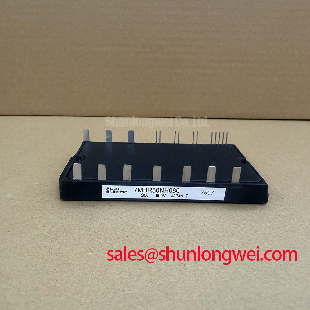
In high-throughput manufacturing lines running precision stepper and brushless DC (BLDC) servo actuators, power converter uptime directly governs assembly floor yield. The Fuji Electric 7MBR50LC060 integrates an input bridge, dynamic brake chopper, and six-pack inverter into a unified Compact PIM package rated at VCES = 600V and continuous collector current IC = 50A at TC = 80°C (Official Datasheet Specification). When facility retrofits demand parallel configurations to handle elevated current demands, thermal and electrical symmetry must be maintained to prevent individual die overload.
The module exhibits a collector-emitter saturation voltage of VCE(sat) = 2.1V at IC = 50A and Tj = 125°C (Official Datasheet Specification). This positive temperature coefficient at rated operating temperatures naturally aids static current sharing, as a warmer branch presents higher channel resistance and shifts steady-state current to cooler branches. However, dynamic current sharing during multi-axis micro-stepping transients requires precise PCB trace matched inductances. For plant modifications requiring higher standalone current ratings rather than parallel balancing, technicians frequently evaluate the single-switch 1MBI200NH-060 to simplify gate drive layout and eliminate mismatch risks.
Turn-Off di/dt Induced V_peak Clamping and Snubber Capacitor Sizing
Fast dynamic responses in servo motion actuators generate steep switching gradients that interact with power loop stray inductance. During turn-off transitions, the collector-emitter voltage peak is governed by the DC link supply plus the induced voltage spike across loop parasitic inductance, expressed as Vpeak = VDC + Lσ × (di/dt). To keep switching overvoltage well within the 600V absolute rating, power stage layouts should target a stray inductance under 25 nH (General Industry Design Consideration) using planar laminated DC busbars and low-ESL film snubber capacitors placed directly across the P and N terminals.
The device provides a robust short-circuit withstand capability rated at tsc = 10 µs under conditions of VCC = 400V, VGE = 15V, and starting junction temperature Tj = 125°C (Official Datasheet Specification). Integrated driver stages must incorporate desaturation detection circuitry set to trip within 3 µs, followed by soft turn-off soft-clamping to prevent destructive overvoltage during hard short events. Detailed switching characterization data is cataloged directly through Fuji Electric Power Semiconductor & IPM Modules documentation.
Thermal Cycling Margins of Internal Braking IGBTs under Repetitive Stop-Start Duty
Repetitive positioning cycles in servo pick-and-place actuators generate continuous kinetic energy regeneration during rapid deceleration. The integrated dynamic braking chopper switch in the 7MBR50LC060 routes this regenerative power into an external ballast resistor to prevent DC link overvoltage trips. Under continuous high-frequency braking, thermal mechanical stress concentrates across the internal silicon-substrate solder layers.
Real-time junction thermal monitoring is facilitated by the internal negative temperature coefficient sensor, featuring a calibrated Integrated NTC Resistance = 5 kΩ at 25°C (Official Datasheet Specification). Plant monitoring systems should tie this NTC output directly into the drive microcontroller thermal shutdown threshold to guard against heat sink clogging or thermal grease degradation. In heavy industrial environments featuring shared DC-bus distribution architectures, high-power feeder stages often utilize the robust 1MBI300L-060 to manage bulk power delivery. Systematic verification workflows and root-cause failure methodologies can be reviewed in our Field Engineer’s Handbook.
Optimizing Gate Drive Loop Geometry to Prevent Cross-Conduction Oscillation
Servo inverter bridges running at high carrier frequencies (8 kHz to 16 kHz) are vulnerable to parasitic dv/dt-induced shoot-through. High switching speeds cause capacitive displacement currents to flow through the gate-collector Miller capacitance (Cres), inducing voltage blips across the gate resistor. Isolating the auxiliary Kelvin emitter terminal from the main high-current emitter power return path eliminates common-path inductive feedback, suppressing gate voltage ringing.
The module ensures operator and signal-level electronics safety with an official Isolation Voltage Viso = 2500V AC for 1 minute between the baseplate and active power terminals (Official Datasheet Specification). Preserving long-term insulation integrity requires strict prevention of moisture and conductive dust accumulation across terminal creepage distances inside industrial electrical enclosures.
⚠️ Maintenance Note: During scheduled drive maintenance (recommended every 24 to 36 months), inspect the thermal interface compound (TIM). Dry or pumped-out silicone paste increases thermal resistance Rth(c-s), accelerating power cycling fatigue. When remounting the module, apply a uniform 100 µm grease layer using a screen stencil and tighten the M5 baseplate mounting bolts in two progressive stages to a final torque of 2.5–3.5 N·m (Standard Industry Design Consideration).