Content last revised on August 28, 2026
Mitsubishi CM75E3U-12H IGBT Module: Engineering Overview & Specs
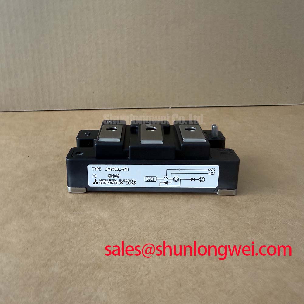
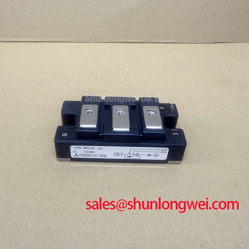
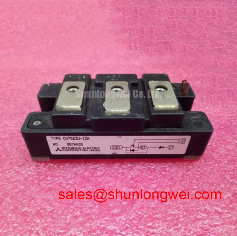
The Mitsubishi CM75E3U-12H is an insulated brake chopper IGBT Module designed for high-efficiency dynamic braking and power switching. Rated at 600V and 75A with a maximum power dissipation of 310W, this unit integrates a discrete super-fast recovery free-wheel diode and an isolated baseplate (2500VRMS). How does it solve dynamic deceleration challenges? It safely absorbs inductive regenerative energy to protect DC-bus capacitors from severe overvoltage faults. For 200V to 400V class variable frequency drives requiring dynamic braking control, this 600V chopper module provides a dependable switching solution.
Key Parameter Overview
Comprehensive Electrical Ratings and Thermal Limits
Evaluating the electrical boundaries and thermal characteristics of the CM75E3U-12H enables engineers to design robust gate drive and thermal cooling networks. Below are the verified technical ratings sourced from the official technical datasheet.
| Parameter Description | Symbol | Rating / Condition | Unit |
|---|---|---|---|
| Collector-Emitter Voltage (G-E Short) | VCES | 600 | V |
| Gate-Emitter Voltage (C-E Short) | VGES | ±20 | V |
| Continuous Collector Current (TC = 25°C) | IC | 75 | A |
| Peak Collector Current (Pulse) | ICM | 150 | A |
| Continuous Emitter Current (Diode Forward) | IE | 75 | A |
| Peak Emitter Current (Diode Pulse) | IEM | 150 | A |
| Maximum Collector Dissipation (TC = 25°C) | PC | 310 | W |
| Isolation Voltage (Main Terminal to Baseplate, AC 1 min) | VISO | 2500 | VRMS |
| Operating Junction Temperature Range | Tj | -40 to +150 | °C |
| Thermal Resistance, Junction to Case (IGBT part) | Rth(j-c) Q | 0.40 (Max) | °C/W |
| Thermal Resistance, Junction to Case (Diode part) | Rth(j-c) D | 0.70 (Max) | °C/W |
| Collector-Emitter Saturation Voltage (IC = 75A, VGE = 15V) | VCE(sat) | 2.4 (Typ) / 3.1 (Max) | V |
Download the CM75E3U-12H datasheet for detailed specifications and performance curves.
Application Scenarios & Value
Optimizing Dynamic Braking and Power Topologies
In heavy-duty motion systems, sudden deceleration forces an electric motor to act as a generator. This dumps kinetic energy straight back into the DC bus link. Without active dissipation, the bus voltage surges past maximum thresholds, tripping drive protections or damaging electrolytic capacitors. The Mitsubishi CM75E3U-12H acts as a controlled dynamic braking switch, routing peak regenerative currents directly through external braking resistors.
Its integrated super-fast recovery diode acts like a one-way relief valve, clamping transient spikes and conducting freewheeling currents during high-speed switching cycles. This layout minimizes parasitic loop inductance compared to discrete implementations. For industrial systems demanding higher voltage headroom, the related CM150E3U-24H offers a 1200V rating, while standard inverter legs can be complemented using the CM150DY-12H.
Key applications include:
- Dynamic brake chopper circuits in industrial motor drives and Variable Frequency Drive (VFD) platforms.
- DC-bus clamping and voltage regulation stages in industrial power supplies.
- High-frequency pulsed power circuits and resistive load switching.
- Switching stages in automated cranes, elevators, and packaging machinery.
Technical Deep Dive
Thermal Structure, Gate Drive, and Switching Architecture
The internal configuration of the CM75E3U-12H pairs an N-channel IGBT with an anti-parallel diode and a series-connected fast-recovery diode in a dedicated chopper topology. The electrical baseplate isolation of 2500VRMS allows multiple power devices to share a single heatsink without external isolation pads. Think of thermal resistance Rth(j-c) as the diameter of an exhaust pipe: at 0.40°C/W, heat generated at the silicon junction vents rapidly into the heatsink base, preventing localized hot spots.
To ensure clean transitions, the gate drive circuit must deliver a stable +15V turn-on voltage while maintaining a low-impedance path to ground or a negative bias during turn-off. Designers should follow robust precision gate drive design practices to prevent dv/dt-induced shoot-through caused by the Miller capacitance under rapid switching transients.
Frequently Asked Questions
Engineering and Application Guidance
What is the circuit configuration of the CM75E3U-12H?
It features a dedicated brake chopper topology consisting of a single 600V 75A N-channel IGBT and discrete super-fast recovery freewheeling diodes inside an electrically isolated module package.
What is the primary thermal benefit of the isolated baseplate in this module?
The 2500VRMS isolation eliminates the need for external ceramic insulators between the module and heatsink, reducing thermal interface barriers and streamlining mechanical assembly.
What gate voltage is recommended for driving the CM75E3U-12H?
A standard gate-to-emitter voltage of VGE = 15V is recommended to achieve the specified VCE(sat) conduction loss, while the absolute maximum limit is ±20V.