

Content last revised on June 5, 2026
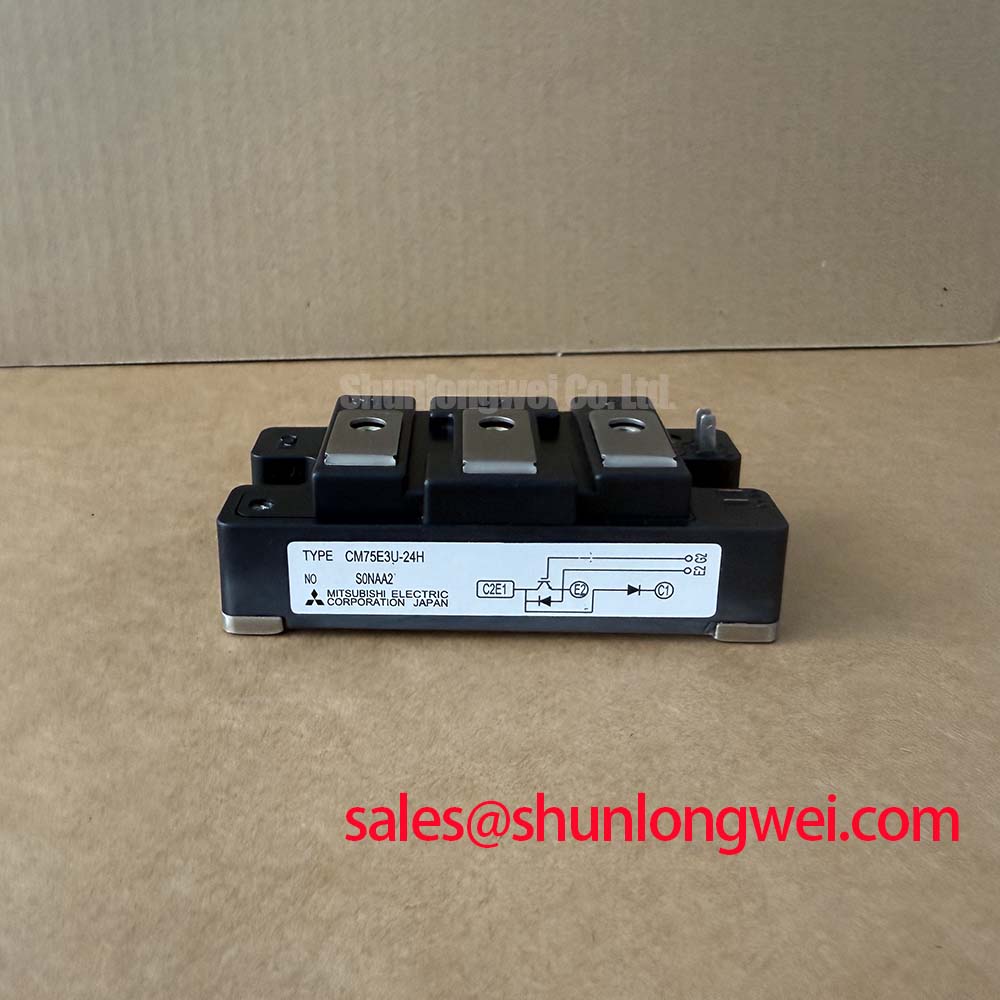
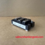
CM75E3U-24H: 1200V 75A Chopper IGBT Module for Dynamic Braking
Engineered for high-stress dynamic braking and boost regulation, the Mitsubishi CM75E3U-24H delivers exceptional thermal management and electrical isolation for heavy-duty 400V/480V industrial AC drives. Key specifications include a 1200V Vces, 75A Ic, and an extremely low Rth(j-c) of 0.21°C/W for the active switching section. This precise architecture minimizes thermal bottlenecks and ensures sustained performance during aggressive deceleration cycles. For engineers questioning its fit in standard industrial motor control, the 1200V blocking voltage guarantees the necessary safety margin against DC-link voltage spikes during regenerative braking events. What is the primary benefit of the CM75E3U-24H isolated baseplate? It drastically simplifies system assembly and enhances thermal management for continuous operation. For 480V VFD braking circuits prioritizing thermal longevity under heavy transient loads, this 1200V/75A chopper module is the optimal choice.
Key Parameter Overview
Decoding the Specs for Enhanced Thermal Reliability
| Functional Group | Parameter | Value / Rating |
|---|---|---|
| Maximum Ratings | Collector-Emitter Voltage (Vces) | 1200V |
| Collector Current (Ic) | 75A | |
| Thermal Metrics | Maximum Power Dissipation (Pc) | 600W |
| Thermal Resistance, Junction to Case (Rth(j-c) IGBT) | 0.21 °C/W | |
| Electrical Characteristics | Collector-Emitter Saturation Voltage (Vce(sat) Max) | 3.7V (at 75A, 15V) |
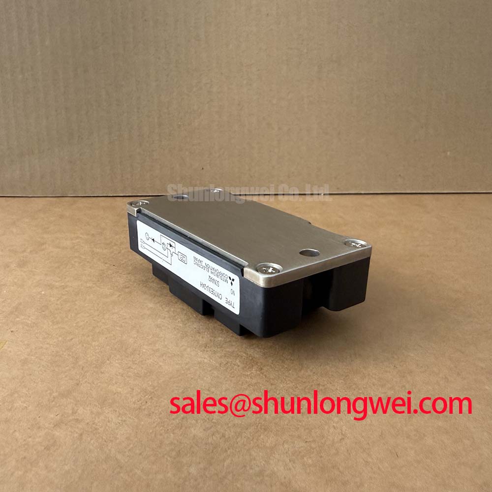
| Isolation Voltage | 2500V (AC 1 minute) |
Download the CM75E3U-24H datasheet for detailed specifications and performance curves.
Application Scenarios & Value
Achieving System-Level Benefits in High-Frequency Power Conversion
In heavy-duty AC motor drives, specifically those controlling industrial conveyor systems or vertical hoists, sudden deceleration forces the motor into a generator state. This rapid mechanical transition drives massive energy back into the DC bus, threatening to trigger critical overvoltage faults. The CM75E3U-24H, operating as a dedicated dynamic brake chopper, seamlessly shunts this excess energy into an external braking resistor. Its capacity to dissipate up to 600W (Pc) guarantees that the inverter survives repetitive, high-energy braking sequences without thermal degradation. Furthermore, the 1200V Vces rating provides an indispensable buffer when the nominal 680V DC-link voltage artificially spikes during these intense regenerative events. For systems requiring higher current handling capacity in similar topologies, the related CM100DY-24H offers a 100A rating to scale up your braking power effectively.
Technical Deep Dive
A Closer Look at the Thermal Management and Baseplate Isolation
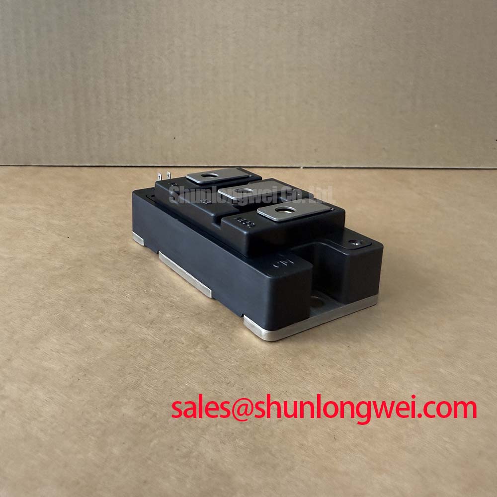
The physical construction of the CM75E3U-24H is centered entirely around its fully insulated baseplate. By completely isolating all active silicon components from the heat-sinking surface, system architects can mount multiple power modules directly onto a single, shared heatsink. This eliminates the necessity for complex, fragile mica insulators or separate thermal zones. Think of the insulated baseplate as a heavy-duty highway barrier—it strictly separates the high-voltage electrical traffic from the structural cooling pavement, preventing catastrophic collisions (short circuits) while still allowing the thermal energy to dissipate rapidly into the environment.
Simultaneously, the remarkably low 0.21°C/W Rth(j-c) acts like a multi-lane exhaust manifold for heat. Just as a high-performance engine needs unrestricted exhaust flow to prevent overheating, the internal silicon relies on this low thermal resistance to flush out the 600W of maximum power loss, safeguarding the Safe Operating Area during aggressive switching operations. To further understand how thermal metrics dictate component lifespan, exploring the core trio of IGBT module selection is highly recommended for optimizing your next design cycle.
Frequently Asked Questions
Engineering Clarifications on the CM75E3U-24H
- How does the Rth(j-c) of 0.21 °C/W directly impact heatsink selection?
A lower junction-to-case thermal resistance dictates that heat transfers much more efficiently to the baseplate. This characteristic empowers engineers to utilize a smaller, more cost-effective heatsink while maintaining safe operating temperatures, directly elevating overall system power density. - Why is the 1200V Vces rating absolutely critical for 480V AC motor drives?
A standard 480V AC line rectifies to an underlying DC bus of approximately 680V. During dynamic braking, this bus can easily surge above 800V. The 1200V rating provides a mandatory, non-negotiable safety buffer to prevent avalanche breakdown during these high-voltage transients. - What makes the "U-Series" chopper configuration distinct for regenerative braking?
The U-Series chopper integrates a primary switching IGBT alongside an anti-parallel free-wheel diode and a specific anode-collector clamping diode. This precise internal topology is pre-optimized at the factory to dump excess DC-link power into a resistor, drastically reducing external PCB layout complexity. - How does the 600W maximum power dissipation (Pc) limit application scaling?
The 600W specification defines the absolute thermal ceiling the module can handle continuously. Design engineers must rigorously calculate their maximum braking duty cycle and switching losses to ensure the average dissipated power remains well below this physical threshold.