


Content last revised on June 21, 2026
PMH150CS1D060 IGBT Module: Engineering Analysis for High-Efficiency Motor Drives
An Integrated 7-in-1 Power Stage for Compact and Reliable Inverters
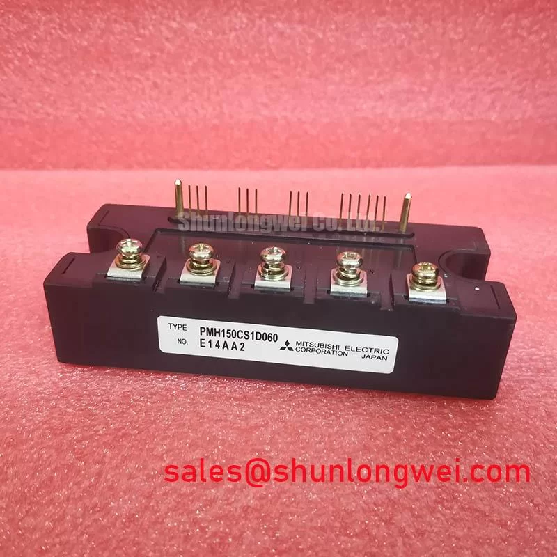
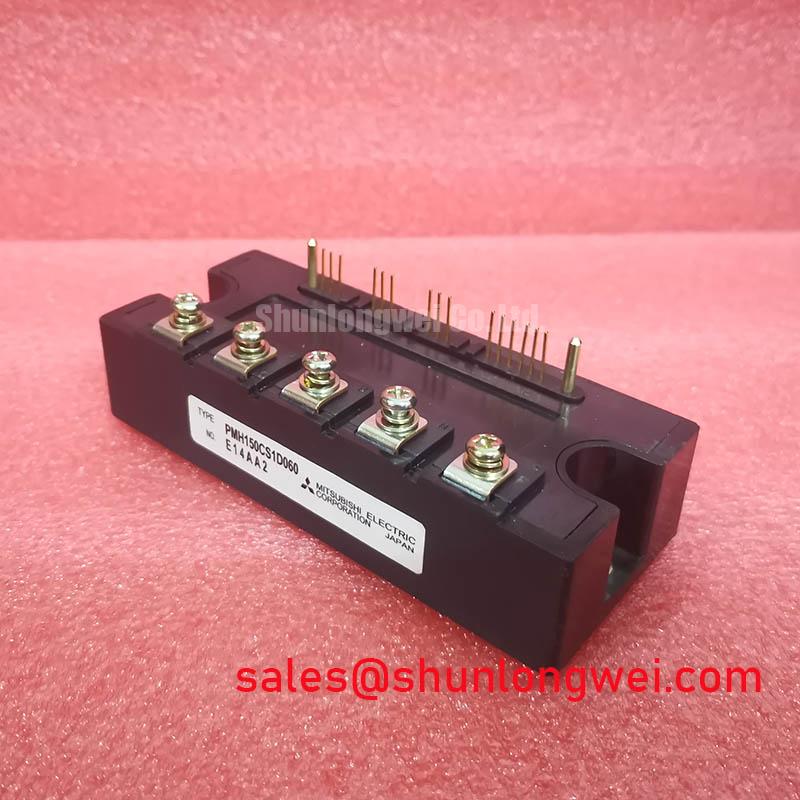
The PMH150CS1D060 from Mitsubishi Electric is a highly integrated 7-in-1 IGBT module delivering robust control for demanding industrial applications. This module consolidates a complete three-phase inverter bridge and a brake chopper circuit into a single, thermally efficient package. Key specifications include 600V | 150A | VCE(sat) 2.2V (typ). Its primary engineering benefits are significant system simplification and optimized switching performance. This design directly addresses the need for compact, reliable power stages in modern variable frequency drives. For systems requiring lower current handling within the same series, the PM75CS1D060 provides a 75A alternative. What is the main benefit of its 7-in-1 topology? A drastic reduction in assembly complexity and system size.
Key Parameter Overview
Decoding the Specs for Integrated Drive Performance
The technical specifications of the PMH150CS1D060 are tailored for balanced performance in motor control applications. The low VCE(sat) minimizes conduction losses, while the switching characteristics are optimized for common PWM frequencies. The integrated thermistor is a critical feature for enabling real-time temperature monitoring and protection.
| Absolute Maximum Ratings (Tj = 25°C unless otherwise noted) | ||
|---|---|---|
| Parameter | Symbol | Value |
| Collector-Emitter Voltage | VCES | 600V |
| Gate-Emitter Voltage | VGES | ±20V |
| Collector Current (DC, Tc=25°C) | IC | 150A |
| Collector Current (Pulse, Tc=25°C) | ICP | 300A |
| Maximum Power Dissipation (Tc=25°C) | PC | 543W |
| Operating Junction Temperature | Tj | -20 to +150°C |
| Electrical Characteristics (Inverter Part) | ||
| Collector-Emitter Saturation Voltage (IC=150A) | VCE(sat) | 2.2V (typ) / 2.7V (max) |
| Turn-On Switching Loss (VCC=300V, IC=150A) | Eon | 20.0mJ/pulse (typ) |
| Turn-Off Switching Loss (VCC=300V, IC=150A) | Eoff | 23.0mJ/pulse (typ) |
| Thermal Resistance (Junction to Case) | Rth(j-c)Q | 0.23°C/W |
Application Scenarios & Value
Achieving System-Level Benefits in Industrial Automation
The PMH150CS1D060 is purpose-built for power conversion systems where space, assembly cost, and reliability are primary design drivers. Its best fit is in compact motor drives and servo controllers rated up to approximately 30 kW.
High-Fidelity Engineering Scenario: Consider the design of a compact Variable Frequency Drive (VFD) for a conveyor belt system in a logistics warehouse. The enclosure has strict dimensional constraints. Using discrete IGBTs and diodes for the inverter and an additional module for the brake chopper would require a larger PCB, complex bus bar arrangements, and multiple mounting procedures. The PMH150CS1D060's 7-in-1 integration solves this challenge directly. It collapses the entire power stage into a single component, minimizing the PCB footprint and simplifying the heatsink design. This integration reduces stray inductance between stages, a key factor in mitigating voltage overshoots during high-speed switching. The result is a more compact, more reliable VFD that is faster to assemble, directly reducing manufacturing costs.
- AC Motor Drives and Servo Drives
- General Purpose Inverters
- Uninterruptible Power Supplies (UPS)
- Industrial Robotics and Automation Systems
This module's architecture exemplifies a strategic approach to power electronics design, where integration is leveraged to enhance both performance and manufacturability. For applications demanding higher power density or exploring different technologies, a thorough review of power semiconductor selection is advisable.
Technical & Design Deep Dive
Analyzing the Impact of Integration on Switching Performance
Beyond the obvious benefits of reduced component count, the integrated design of the PMH150CS1D060 has a direct and positive impact on its electrical performance. In a power circuit, the physical layout—the length and geometry of the copper traces and bus bars—creates parasitic inductance. This stray inductance is a major source of concern for engineers, as it can cause significant voltage overshoots and ringing when the IGBTs switch at high speeds.
Think of stray inductance like a small, unwanted spring in a rigid mechanical system. When you try to stop the system abruptly (turn off the IGBT), the spring's stored energy causes oscillations and stress. The PMH150CS1D060 minimizes this "spring effect" by placing all critical power components (the inverter IGBTs, freewheeling diodes, and brake chopper) in close proximity within a single, optimized layout. This internal design drastically shortens the current paths compared to a discrete solution, resulting in lower overall stray inductance. For the design engineer, this translates to cleaner switching waveforms, reduced EMI generation, and improved reliability, as the semiconductor devices are subjected to lower voltage stress. What does lower voltage stress mean for reliability? It directly contributes to a longer operational life and a more robust system.
Frequently Asked Questions (FAQ)
What is the primary advantage of the integrated brake chopper in the PMH150CS1D060?
The integrated brake chopper provides a built-in solution for dissipating regenerative energy, which occurs when a motor decelerates rapidly. Including it within the module eliminates the need for an external chopper circuit, simplifying the design of the DC bus, reducing component count, and saving significant cabinet space in applications like elevators or cranes that require dynamic braking.
How does the VCE(sat) of 2.2V (typ) influence the thermal design of a system?
The Collector-Emitter Saturation Voltage, or VCE(sat), is the voltage drop across the IGBT when it is fully on. This parameter is a primary determinant of conduction losses (Power Loss = VCE(sat) * IC). A lower VCE(sat) like the 2.2V of this module means less energy is converted into heat during operation. This directly reduces the thermal load on the heatsink, potentially allowing for a smaller, lighter, and lower-cost cooling solution to maintain the junction temperature within safe operating limits.
Is this 600V module suitable for use on a 400/480V AC line?
Yes, a 600V VCES rating provides the necessary voltage margin for operation on a 200-240V AC line. While it can be used in some 400V AC applications, designers must carefully account for DC bus voltage levels, potential transients from the line, and regenerative braking, which can cause the DC bus voltage to rise significantly. For robust designs on 480V AC systems, engineers typically specify IGBT modules with a 1200V rating to ensure a sufficient safety margin against overvoltage conditions.
Technical Inquiry and Sourcing
To evaluate the PMH150CS1D060 for your specific application, please consult the official datasheet for detailed performance graphs and application notes. For inquiries regarding availability and procurement, our team can provide the necessary information to support your design and purchasing cycles.