


Content last revised on June 18, 2026
PM150CSD120 Datasheet, Specs & Analysis: 1200V/150A Intelligent Power Module
Product Overview & Key Features
An Integrated Solution for High-Reliability Motor Drives
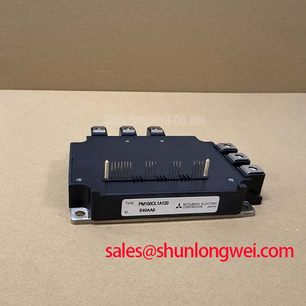
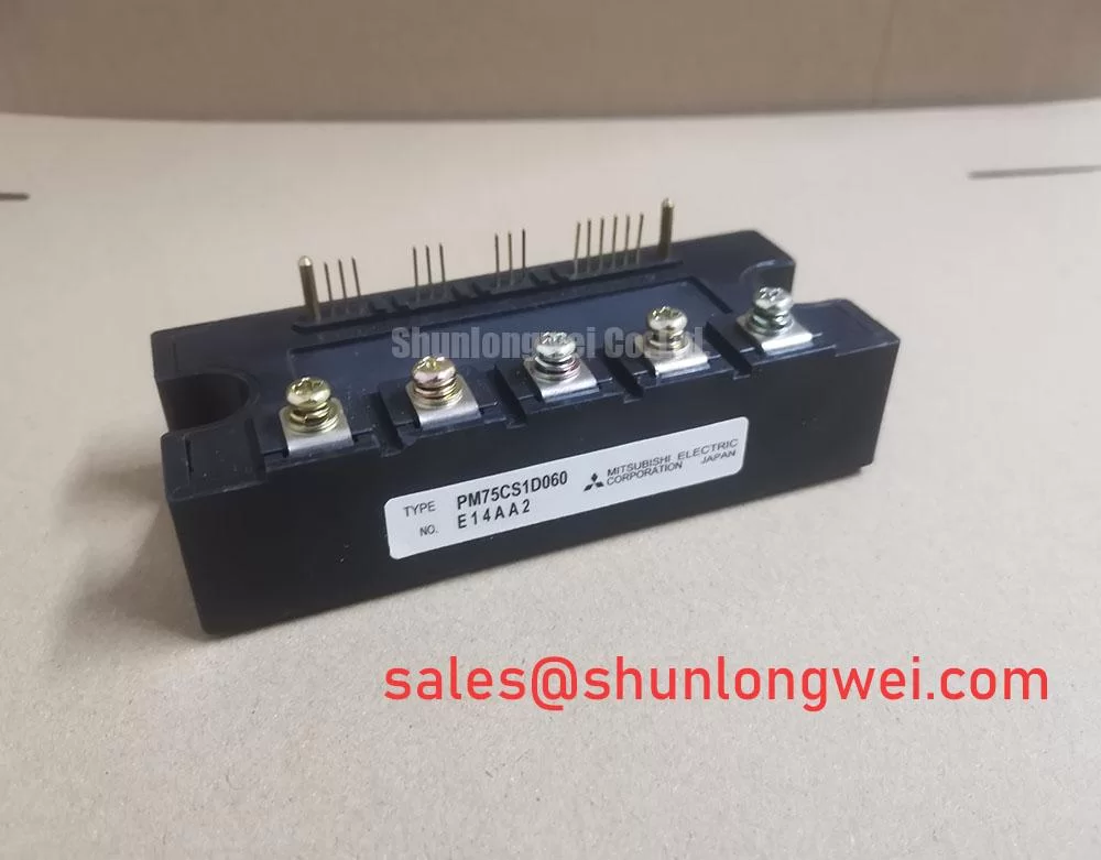
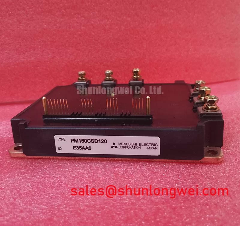
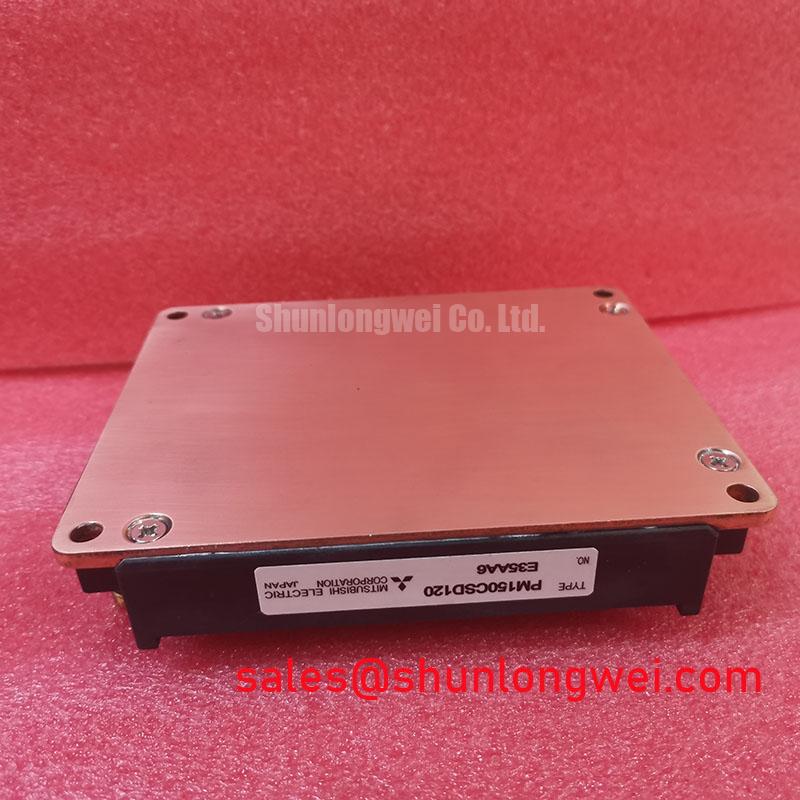
The Mitsubishi PM150CSD120 is an Intelligent Power Module (IPM) designed to maximize system reliability and simplify the design of three-phase power conversion systems. It integrates a 1200V/150A IGBT inverter bridge with optimized gate drivers and a suite of protection circuits into a single, thermally efficient flat-base package. Its core specifications include: 1200V | 150A | Integrated OC, SC, OT, & UV Protection. The key engineering benefits are significantly enhanced system robustness and a streamlined thermal management design process. This module's integrated protection architecture provides a fast-acting defense against common failure modes, operating much quicker than microcontroller-based monitoring. For industrial motor drives up to ~45kW where uptime is critical, the PM150CSD120's built-in safeguards offer a decisive engineering advantage.
What is the main benefit of an IPM like the PM150CSD120? It combines power switching, gate drive, and protection circuits, drastically reducing design complexity and improving reliability.
Key Parameter Overview
Decoding the Specs for Enhanced Thermal Reliability
The electrical and thermal characteristics of the PM150CSD120 are specified to ensure dependable performance in demanding industrial applications. The parameters below highlight its capacity for robust power handling and effective heat dissipation, which are fundamental to long-term operational stability. Understanding the thermal resistance is key; think of it like the diameter of a pipe. A lower value, like the 0.20 °C/W for the IGBT in this module, represents a wider pipe, allowing performance-damaging heat to be evacuated from the semiconductor chip more efficiently.
| Parameter | Symbol | Conditions | Value |
| Collector-Emitter Voltage | Vces | Vge = 0V | 1200V |
| Collector Current (DC) | Ic | Tc = 25°C | 150A |
| Collector-Emitter Saturation Voltage | Vce(sat) | Ic = 150A, Vge = 15V | 2.7V (Typ.) / 3.4V (Max.) |
| Power Dissipation | Pc | Tc = 25°C, Per 1 IGBT | 625W |
| Thermal Resistance (Junction to Case) | Rth(j-c) | IGBT Part | 0.20 °C/W |
| Short Circuit Withstand Time | tsc | Vcc = 600V, Vge = 15V, Tj = 125°C | ≥ 10µs |
| Isolation Voltage | Viso | Terminals to Baseplate, AC 60Hz | 2500 Vrms |
Download the PM150CSD120 datasheet for detailed specifications and performance curves.
Application Scenarios & Value
Achieving System-Level Benefits in Industrial Motion Control
The PM150CSD120 is engineered for power conversion applications where operational reliability is non-negotiable. Its primary use is in AC motor drives, including general-purpose inverters and high-performance Servo Drive systems.
Consider the engineering challenge in a CNC milling machine's spindle drive. A sudden tool jam can cause a massive overcurrent or even a short-circuit condition in the motor windings. In a system using discrete IGBTs, the external protection circuit and microcontroller must detect this event and shut down the gate signals within microseconds to prevent catastrophic failure. The inherent latency in this external loop can be too long, leading to IGBT destruction and costly machine downtime. The PM150CSD120 solves this by integrating fast-acting Short-Circuit (SC) and Over-Current (OC) protection directly at the chip level. This on-board defense system acts almost instantaneously, protecting the power stage before an external controller could even register the fault, thus preserving the integrity of the drive. This built-in resilience is critical for maintaining productivity in demanding Motion Control environments.
This module's 150A rating is well-suited for a wide range of motor sizes. For systems with lower power requirements, the related PM100CSD120 provides a 100A alternative within the same family. Conversely, for applications demanding higher power output, a module like the 2MBI200NB-120 offers a 200A current rating.
Frequently Asked Questions (FAQ)
Engineering Inquiries for the PM150CSD120
How does the integrated short-circuit (SC) protection in the PM150CSD120 enhance drive reliability compared to discrete solutions?
The integrated SC protection provides a much faster response time by eliminating the propagation delays associated with external current sensors, comparators, and microcontroller intervention. This near-instantaneous shutdown capability is crucial for protecting the IGBTs during severe fault events, directly increasing the mean time between failures (MTBF) of the power drive.
What is the function of the 'Fo' (Fault Output) pin and how should it be implemented in a control system?
The 'Fo' pin is an open-collector output that signals a fault condition (Over-Current, Short-Circuit, Over-Temperature, or Under-Voltage) to the host microcontroller. In a typical implementation, this pin is connected to an interrupt input on the controller via a pull-up resistor. When a fault occurs, the Fo pin goes low, triggering the interrupt and allowing the system to initiate a safe shutdown procedure and log the error for diagnostics.
Can the PM150CSD120 be driven directly from a microcontroller's PWM output?
No, direct connection is not recommended. While it is an IPM (Intelligent Power Module), it requires specific logic-level control signals (typically 15V) for its inputs (UP, VP, WP, UN, VN, WN). The microcontroller's PWM signals should be passed through a level-shifter or buffer stage to provide the correct voltage and current drive for these control inputs. It is also essential to implement proper dead-time generation in the PWM signals to prevent shoot-through.
Technical Deep Dive
Anatomy of the Integrated Protection System
The core value of the PM150CSD120 lies in its multi-layered, autonomous protection system. This internal network functions like the advanced safety systems in a modern vehicle—constantly monitoring conditions and reacting faster than an external operator to prevent disaster. The Short-Circuit Withstand Time (tsc) of ≥ 10µs is not just a rating; it is the critical time window the internal circuitry has to detect a fault and safely turn off the IGBT. Here’s how the key protections work in concert:
- Short-Circuit (SC) and Over-Current (OC) Protection: This is the first line of defense. By monitoring the IGBT's saturation voltage (Vce(sat)), the module can detect a desaturation event indicative of an extreme current condition. It then initiates a "soft turn-off" to manage the inductive voltage spike (di/dt) and sends a fault signal.
- Over-Temperature (OT) Protection: An integrated temperature sensor located near the IGBT chips provides real-time thermal feedback. If the junction temperature exceeds the safe limit (typically ~150°C), the module shuts down and flags a fault, preventing thermal runaway.
- Under-Voltage (UV) Lockout: This crucial feature ensures the IGBT gates are never driven with insufficient voltage. A low gate voltage would cause the IGBT to operate in its linear region, leading to extremely high power dissipation and rapid failure. The UV lockout circuit disables the module if the control supply voltage drops below a safe threshold.
This tightly integrated approach, detailed in resources like the Mitsubishi Electric power module documentation, ensures that the device protects itself reliably, allowing designers to focus on system-level control logic rather than discrete protection hardware.
Adopting an integrated module like the PM150CSD120 is a strategic design choice that shifts focus from component-level survival to system-level reliability. By entrusting critical protection to an optimized, self-contained unit, engineering teams can reduce development cycles and deliver a more robust end-product with a lower total cost of ownership.