


Content last revised on September 30, 2026
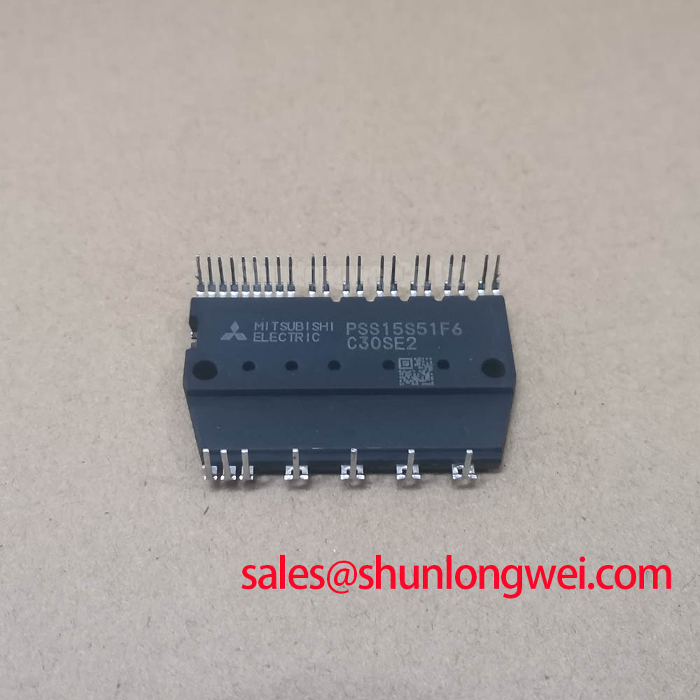
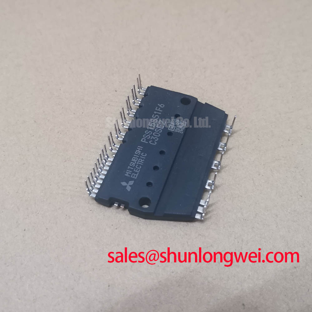
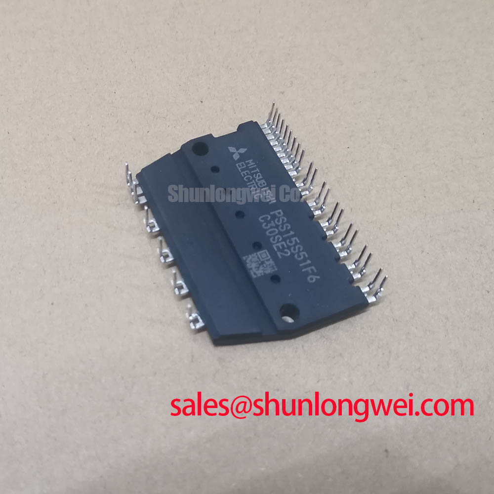
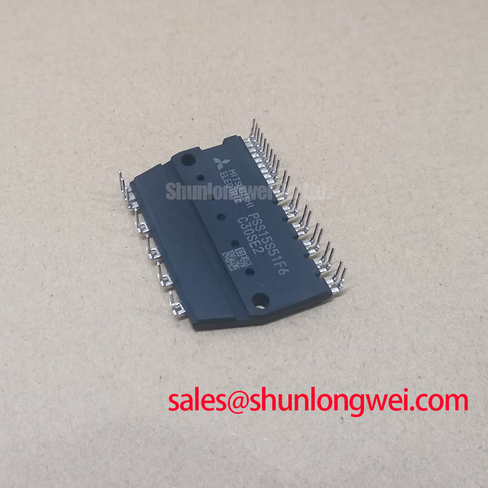
Assembly Integrity and Layout Architecture for PSS15S51F6
| Model | PSS15S51F6 |
|---|---|
| Manufacturer | StarPower |
| Product category | IGBT Module |
| Package | Power Module |
| Voltage and current ratings | Numerical ratings were not supplied; neither rating can be used as a replacement criterion without the original manufacturer documentation. |
Measure the cold resistance between each identified power terminal of PSS15S51F6 and compare the results with an undamaged reference before fitting the module to a power stage. Record meter polarity and probe positions: a reading without its terminal pair is of little use when checking an incoming part. Use the equipment schematic and the manufacturer pinout to distinguish an expected conduction path from an unintended short. If the pinout is unavailable, do not infer terminal functions from their physical arrangement.
In a prospective commercial string inverter or microgrid energy storage installation, charging and discharging can repeatedly change device loading. As a Design Consideration, inspect the mounting surface, thermal interface and busbar alignment for conditions that could aggravate temperature swings. Keep the power loop compact to limit switching overshoot, but establish electrical clearances from the equipment design and its applicable requirements rather than from the appearance of this package. During commissioning, compare measured switching peaks with the documented device rating and the system DC link.
For repair evaluation, match the original part number, terminal map, mounting interface and documented electrical limits. The separately listed FF650R17IE4D_B2 can be examined as a separate sourcing candidate, but it is not an established drop-in replacement for PSS15S51F6. Terminal arrangement, drive requirements and thermal fit would all need independent verification.
Preventing Spurious Faults Through Heatsink Contact and Protection Checks
Inspect the heatsink contact pattern when temperature-related trips appear after a module change. Uneven transfer material, debris or a distorted mounting surface can impair contact; the trip alone does not identify which condition is present. As a Design Consideration, apply thermal interface material uniformly and follow the documented mounting sequence and torque for the actual module and hardware. Do not adopt a target film thickness or screw torque without a qualified assembly procedure.
Check the protection path separately from the thermal joint. Compare the installed semiconductor fuse’s published clearing characteristics with the equipment fault study and the module’s documented surge and short-circuit limits. A fast fuse cannot be assumed to protect every semiconductor fault: available fault current, DC-link energy and the controller’s shutdown response affect the result. The applicable coordination decision belongs to the system design.
For cold incoming inspection, use the meter’s diode function only across conduction paths confirmed by the manufacturer terminal diagram. Log forward readings with the same meter, polarity and temperature conditions used for a known-good comparison; do not impose a generic pass voltage on an unidentified path. 💡 Bench Tip: Discharge the DC link and verify it is de-energized before moving probes between power terminals.
If the assembly includes a temperature sensor, identify it from its wiring documentation before testing it. A resistance change with temperature is the general behavior of an NTC thermistor; its presence, calibration and terminal assignment must not be presumed for PSS15S51F6.
Field Diagnostics and Commissioning: Voltage Margin
Capture the DC-link voltage and the device turn-off waveform when unexplained trips coincide with high bus voltage or load transitions. Examine the measured peak against the manufacturer’s voltage rating, once obtained, under the equipment’s operating conditions. The supplied product information gives no numerical voltage rating, so it cannot support a calculated headroom figure or a safe operating limit.
As a Design Consideration, installation conditions may warrant a separate reliability review, but no single-event burnout rate, altitude derating or lifetime estimate can be assigned to this model from the information provided. Keep that review distinct from a fault diagnosis. Probe placement, busbar inductance and gate-drive behavior are more immediate checks when a switching waveform shows overshoot. Minimize parasitic loop inductance to reduce turn-off peaks, then validate the resulting margin in system switching tests.
Inspect gate waveforms for unintended turn-on during rapid voltage transitions. Gate-to-collector coupling and the Miller interval are useful diagnostic concepts, not evidence of a specified capacitance, gate charge or built-in clamp in this module. If the equipment uses active clamping, verify its operation against the actual driver circuit and device documentation. Precision Gate Drive Design provides further context for that circuit-level assessment; ROHM’s IGBT technical resources provide background on IGBT switching behavior, not specifications for this StarPower part.
Field Diagnostics and Commissioning: Current Distribution
Compare current waveforms in each parallel path if one position runs hotter than its neighbors. Confirm sensor placement and calibration first, then check busbar symmetry, connection resistance and gate-drive timing. A cold resistance check can reveal a gross connection discrepancy, but it cannot establish dynamic current sharing during switching.
As a Design Consideration, static sharing depends in part on how on-state voltage varies with current and temperature; dynamic sharing also depends on differences in gate-loop and power-loop impedance. No VCE(sat) temperature characteristic was supplied for PSS15S51F6, so positive temperature coefficient behavior must not be assumed. Compare the manufacturer’s curves under the intended operating conditions before using that characteristic in a parallel-device assessment.
If turn-on or turn-off currents diverge, inspect the routing and connections of each gate and return path, then compare waveforms at equivalent measurement points. Adjusting damping or protection settings is a system-level decision: preserve stable switching while checking peak voltage, current imbalance and junction-temperature limits against documented ratings. Record those observations alongside the cold terminal readings so the next incoming inspection has a traceable reference.