


Content last revised on October 1, 2026
SKM200GAR125D in DC Link Overvoltage and Braking Faults
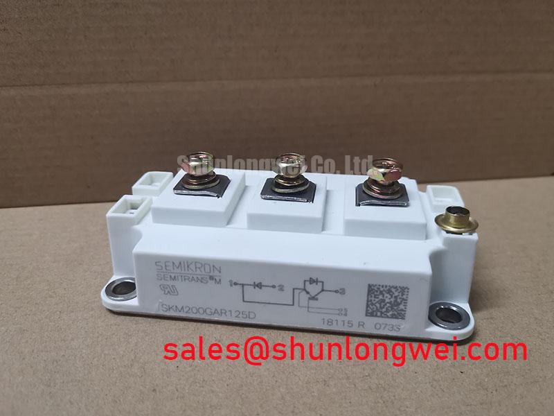
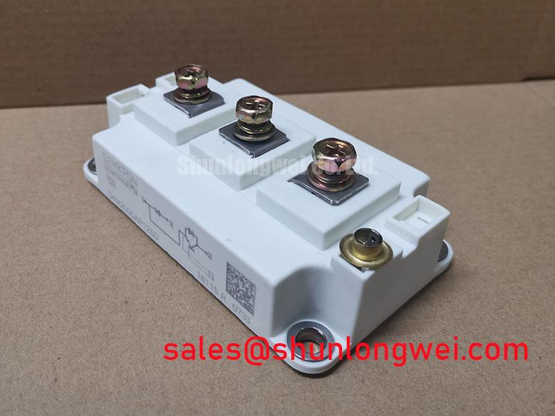
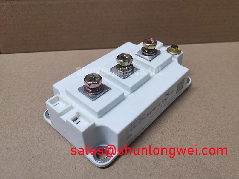
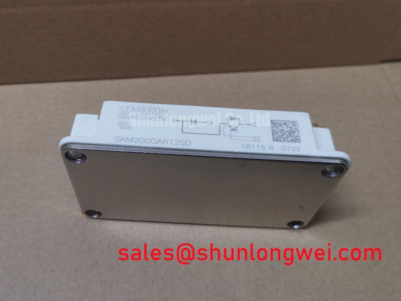
SKM200GAR125D is a Semikron IGBT module in the SEMITRANS package, rated at 1200 V and 200 A (Official Specification).
Capture the DC link voltage during a controlled deceleration and compare the peak with the drive’s recorded overvoltage trip. A trip that occurs as the motor slows can involve returned motor energy, braking control, or switching transients; the trip record alone does not isolate the SKM200GAR125D. Check whether the braking path commanded by the controller actually conducts, then inspect the resistor circuit and its connections with the equipment safely isolated.
The module’s 1200 V voltage rating (Official Specification) is a device boundary, not a permissible DC link operating voltage or a braking threshold. As a Design Consideration, the braking switch and resistor must be assessed together against the drive’s motor energy, deceleration profile, control behavior, and resistor thermal capacity. Whether the SKM200GAR125D occupies that switching position depends on the equipment schematic. Do not infer an internal braking function from the module’s current and voltage ratings.
Trace the physical path from the DC link capacitors through the switching assembly and braking components. Loose bus connections or an extended current loop can raise the voltage seen at a switching device even when the controller reports an ordinary link voltage between events. A metal oxide varistor, where the equipment design includes one, has a different task from an energy rated braking resistor: its coordination with clamps and other protection parts should be checked against the circuit documentation rather than treated as a substitute for braking capacity. The Semikron Danfoss SEMITRANS product information provides package family context; the installed drive’s schematic establishes the actual protection network.
For an electric forklift or warehouse traction drive, this is a compatibility assessment, not an assumed application of the module. Compare the existing module’s circuit connections, mounting arrangement, and control interface before treating its ratings as evidence of interchangeability.
Current Sharing, Commutation, and Parameter Matching
Probe the gate to emitter and collector to emitter waveforms at the affected switching position, using measurement methods appropriate to the drive’s voltage and grounding arrangement. Unequal switching behavior can originate in gate wiring, driver timing, bus geometry, or device characteristics. Compare the suspect position with a known working phase under comparable conditions before attributing the difference to the SKM200GAR125D.
The 200 A current rating (Official Specification) does not, by itself, establish allowable current in a particular enclosure. Heat sink condition, cooling airflow, switching losses, and the equipment’s operating cycle affect the installed thermal result. When parallel devices are present, symmetrical power and gate paths are a Design Consideration for dynamic sharing. A temperature dependent on state characteristic may influence static sharing, but no current sharing guarantee or specific temperature coefficient should be assigned to this model without its characteristic curves and the circuit operating point.
Check commutation waveforms for ringing and overshoot at the device terminals rather than judging behavior solely from a controller alarm. Where a freewheeling diode participates in the installed topology, its recovery behavior and the surrounding loop inductance can affect voltage transitions. A snubber may help control those transitions, but its placement and values are system determined and should be validated by switching tests. The module alone does not establish the equipment’s radiated emissions performance.
During a replacement evaluation, SKM400GAL125D can be included in a documented comparison of ratings, terminal layout, thermal interface, and switching characteristics; its different model designation is not proof of interchangeability. At the wider converter level, SKIM401GD128D is a separate module to assess only where the equipment schematic calls for a corresponding power stage. The Semikron Danfoss power electronics hub is a useful reference for manufacturer product family documentation.
Assembly Integrity, Cooling, and Environmental Exposure
Inspect the heat sink contact area and measure temperature trends at comparable loads when an installed module runs hotter than its neighboring positions. Look for obstructed airflow, uneven mounting contact, aged interface material, and discoloration around power terminals. These observations narrow the fault search, but none proves a single cause without electrical and thermal checks.
Maintenance Note: Isolate and discharge the drive before disturbing module terminals, then verify the specified fastening procedure during reassembly.
Keep the mounting surface clean and assess its flatness and finish against the assembly requirements. Apply thermal interface material using the equipment’s approved method; excess material can be as troublesome as poor coverage. Recheck terminal tightness with the specified hardware and procedure rather than borrowing a torque value from another SEMITRANS assembly. Record heat sink cleaning, interface material inspection, and terminal checks in the maintenance history so a rising temperature trend can be investigated before it becomes a repeat shutdown.
Moisture and condensation deserve attention when a drive moves between cold storage and warmer operating areas. As a Design Consideration, inspect enclosure seals, airflow paths, and signs of condensation before energizing equipment that has experienced a substantial temperature change. The 1200 V device rating does not establish clearance requirements for the complete assembly; insulation spacing and contamination control belong to the equipment design and applicable installation rules.
Altitude and radiation related failure mechanisms cannot be converted into a failure in time rate for the SKM200GAR125D from the supplied voltage and current ratings. If an installation has unusual altitude or reliability requirements, the system engineer should obtain device specific reliability guidance and assess DC link voltage exposure in that context. No site lifetime or single event burnout figure follows from the module nameplate alone.
Turn Off Overshoot and Gate Drive Fault Isolation
Measure the collector to emitter peak at turn off while observing the gate waveform if shutdowns coincide with switching edges. Compare the measured peak with the 1200 V device rating (Official Specification), accounting for measurement setup and the full range of equipment operating conditions. A DC link reading taken between switching events can miss the brief peak that matters at the module terminals.
As an Engineering Calculation, the turn off peak can be considered as the DC link voltage plus the voltage produced by stray loop inductance during current change. That relationship explains why bus layout, snubber placement, and switching speed must be evaluated together; it does not supply a universal inductance target or capacitor value. Keep the high current loop compact and its return path deliberate, then verify the resulting waveform on the assembled drive. Check the equipment schematic before adjusting a clamp or snubber, since a change in one branch can shift stress elsewhere.
Inspect the driver command and the actual gate waveform separately. A controller may request adequate dead time while unequal propagation delays through optocouplers or digital isolators reduce the effective separation at the switches. As a Design Consideration, verify driver timing and common mode transient behavior at the installed operating conditions rather than assigning a fixed delay or immunity requirement to the module. For questions about off state gate behavior during rapid voltage transitions, Evolution of Negative Off-Bias Gate Drive Circuits provides related circuit background; the required gate drive settings remain dependent on the device documentation and tested drive design.
If the waveform differs after service work, retrace gate and emitter connections, driver supply integrity, and busbar seating before changing protection settings. Repeat the measurement at a controlled load, document the test conditions, and compare the result with the equipment’s established waveform or a sound parallel phase.