Content last revised on June 23, 2026
UM100CDY-10 IGBT Module: Technical Data & Application Guide for 100A/500V Power Systems
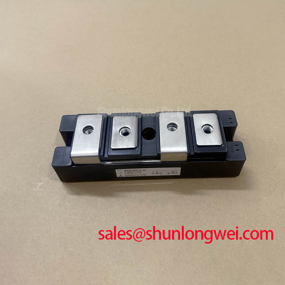
An In-Depth Look at the Mitsubishi UM100CDY-10 C-Series IGBT
The Mitsubishi UM100CDY-10 is a C-Series dual IGBT module designed for robust and reliable power switching in 200V-class industrial systems. With core specifications of 500V | 100A | 390W Pc, this module provides two primary engineering benefits: simplified thermal design and proven operational reliability. It directly addresses the need for a durable power stage in applications where a 500V rating offers the ideal safety margin for 200-240V AC line-operated equipment without the performance trade-offs of higher-voltage alternatives. For cost-effective 200-240V motor drives requiring proven thermal performance, the UM100CDY-10 offers a robust and straightforward solution.
Application Scenarios & Value
System-Level Benefits in Industrial Motor Control and Power Conversion
The UM100CDY-10 is engineered for medium-power applications where long-term reliability is a primary design driver. Its dual IGBT (half-bridge) configuration makes it a fundamental building block for the power stages of AC servo drives, general-purpose inverters, and DC-DC converters. What is the primary benefit of its integrated, isolated base? It significantly simplifies assembly and enhances thermal performance by allowing direct mounting to a heatsink without extra insulating layers.
Consider the design of a power inverter for a factory automation system, such as a conveyor belt motor drive operating on a 220V AC line. A key challenge is ensuring consistent performance and preventing thermal overload during continuous, high-duty-cycle operation. The UM100CDY-10's specified 390W collector power dissipation (Pc), combined with its low thermal resistance, provides the necessary capacity to manage heat effectively. This robust thermal design is crucial for minimizing downtime and maintenance costs in industrial environments. The module's straightforward gate drive requirements also simplify the control circuitry, contributing to a more streamlined and cost-efficient overall system design. For systems requiring higher current handling at 1200V, the related 2MBI200nb-120 offers an alternative performance profile.
Key Parameter Overview
Engineering Specifications and Their Impact on System Reliability
The technical specifications of the UM100CDY-10 are tailored for efficiency and durability in its target applications. The following table highlights key parameters and interprets their direct engineering implications, moving beyond simple values to explain their role in system-level design. This approach helps in evaluating the module's suitability for specific power conversion challenges.
| Parameter | Rating (Tj=25°C) | Engineering Implication |
|---|---|---|
| Collector-Emitter Voltage (Vces) | 500V | Provides a secure voltage margin for applications running on 200-240V AC lines, protecting against transient voltage spikes. |
| Collector Current (Ic) | 100A | Defines the continuous current handling capability, suitable for medium-power industrial motors and inverters. |
| Collector-Emitter Saturation Voltage (VCE(sat)) | 2.7V (Max) | Directly impacts conduction losses. A lower VCE(sat) results in less heat generated during operation, improving overall system efficiency. |
| Collector Power Dissipation (Pc) | 390W | This is the module's thermal budget. It dictates the maximum power that can be dissipated, a critical factor for effective thermal management and heatsink selection. |
| Thermal Resistance (Rth(j-c)) | 0.32°C/W (IGBT) | Measures how effectively heat is transferred from the semiconductor junction to the case. A lower value signifies superior heat transfer, leading to lower operating temperatures and higher reliability. |
| Isolation Voltage (Viso) | 2500V | Ensures electrical safety and simplifies mounting by allowing multiple modules to share a common, non-isolated heatsink, reducing assembly complexity. |
Industry Insights & Strategic Advantage
Strategic Value of Proven Technology in Legacy and Cost-Sensitive Systems
In an industry often focused on the latest semiconductor technology, components like the Mitsubishi UM100CDY-10 C-Series retain significant strategic importance. For maintenance, repair, and operations (MRO) of existing industrial equipment, using original or equivalent specification components is paramount for ensuring system integrity and avoiding costly re-qualification. This module provides a direct, reliable solution for servicing a large installed base of industrial machinery.
Furthermore, for new designs in cost-sensitive markets, leveraging proven and well-understood technology can be a distinct advantage. The UM100CDY-10's performance characteristics are thoroughly documented, removing design uncertainties and accelerating the development timeline. The focus shifts from managing the risks of next-generation components to optimizing a system around a known-reliable power stage. This approach prioritizes a low total cost of ownership (TCO) and field-proven reliability over marginal gains in switching frequency or power density that may not be required by the target application.
Frequently Asked Questions (FAQ)
Practical Questions for Design and Implementation
What is the significance of the 500V Vces rating in system design?
The 500V rating is specifically optimized for systems operating on 200V to 240V AC lines. It provides sufficient headroom to safely absorb voltage transients and overshoots common in industrial environments, without incurring the higher switching losses and costs associated with oversized 1200V modules.
How does the VCE(sat) of 2.7V impact thermal design?
VCE(sat) is the voltage drop across the IGBT when it's fully on. This voltage, multiplied by the collector current, determines the conduction power loss. A VCE(sat) of 2.7V at 100A means 270W of heat is generated from conduction losses alone. This value is a critical input for calculating the required heatsink performance to keep the junction temperature within safe operating limits.
What does the thermal resistance Rth(j-c) of 0.32°C/W mean for heatsink selection?
This value quantifies the temperature rise from the semiconductor junction to the module's case for every watt of dissipated power. For example, if the IGBT is dissipating 100W, its junction will be 32°C hotter than its case. This parameter is essential for calculating the maximum allowable thermal resistance of the heatsink to prevent the device from overheating under worst-case load conditions.
What are the typical gate drive requirements for the UM100CDY-10?
As a standard C-Series IGBT, it is typically driven with a gate-emitter voltage (Vge) of +15V for turn-on and 0V to -10V for turn-off. Using a negative voltage for turn-off provides better noise immunity and helps prevent parasitic turn-on, enhancing the reliability of the system, especially in electrically noisy PWM-driven applications.
What is the key advantage of the module's isolated base?
The 2500V AC isolation rating allows the module to be mounted directly onto a grounded heatsink without any additional thermal interface pads like mica or silicone. This not only simplifies the mechanical assembly process but also improves thermal conductivity and long-term reliability by eliminating a potential point of failure and degradation in the thermal path.
An Engineer's Perspective on the UM100CDY-10
From a design engineer's viewpoint, the UM100CDY-10 is a foundational workhorse. It is not designed to push the boundaries of switching speed or power density but to provide a dependable, easily implemented power switching solution for a specific and widely used voltage class. Its value lies in its predictability. The well-defined thermal characteristics and standard footprint reduce design risks, making it an excellent choice for industrial applications where equipment longevity and consistent, reliable operation are the most critical metrics of success. It represents a practical balance of performance, cost, and proven field reliability for medium-power conversion systems.