
Content last revised on September 19, 2026
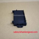
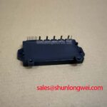
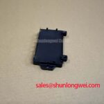
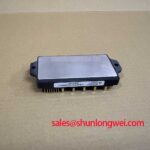
PM52AUBZ060-1 Inspection and Application Overview
With the drive isolated and the DC link discharged, first verify that the installed PM52AUBZ060-1 has no visible transfer-mold damage, loose power connections, or unintended low-resistance shorts between the inverter output terminals and the DC bus.
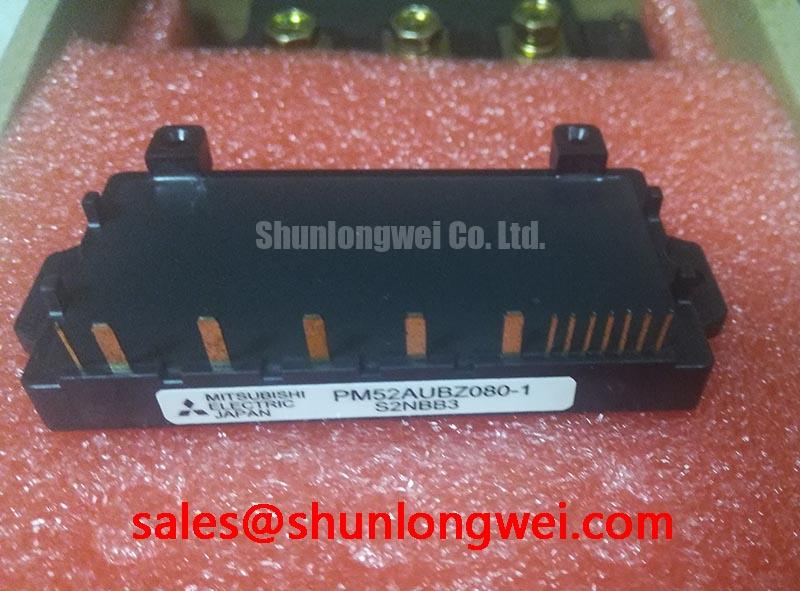
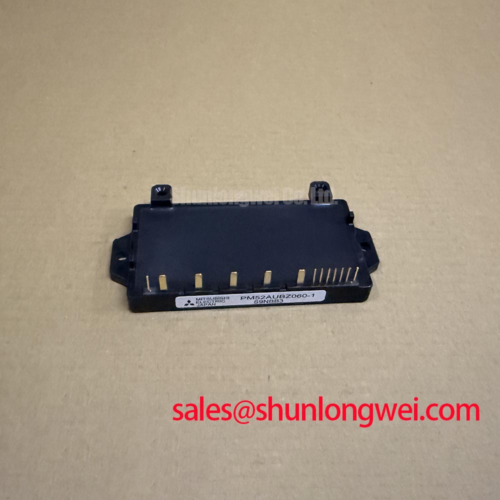
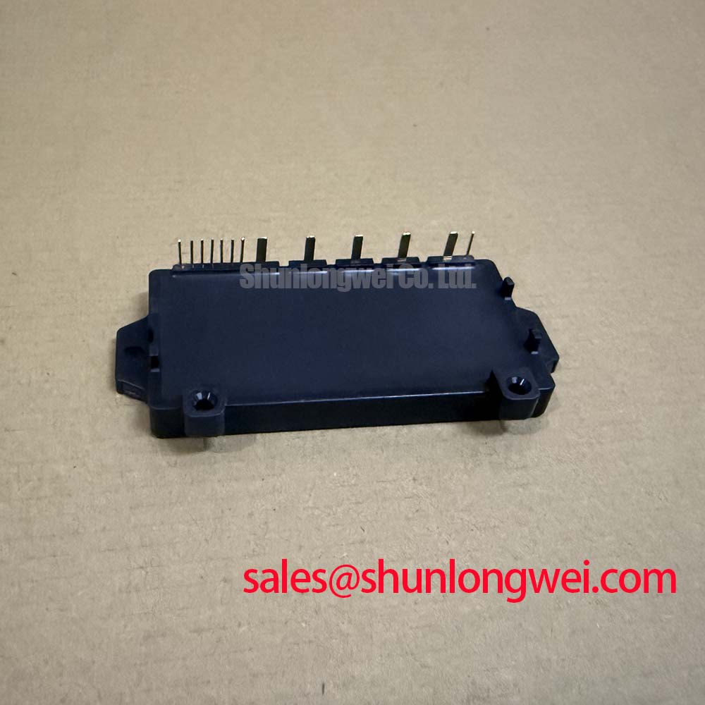
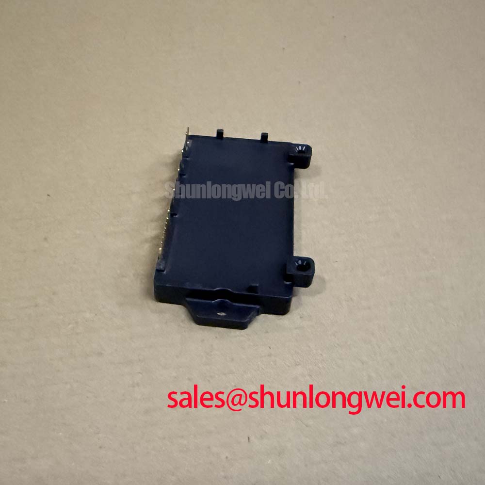
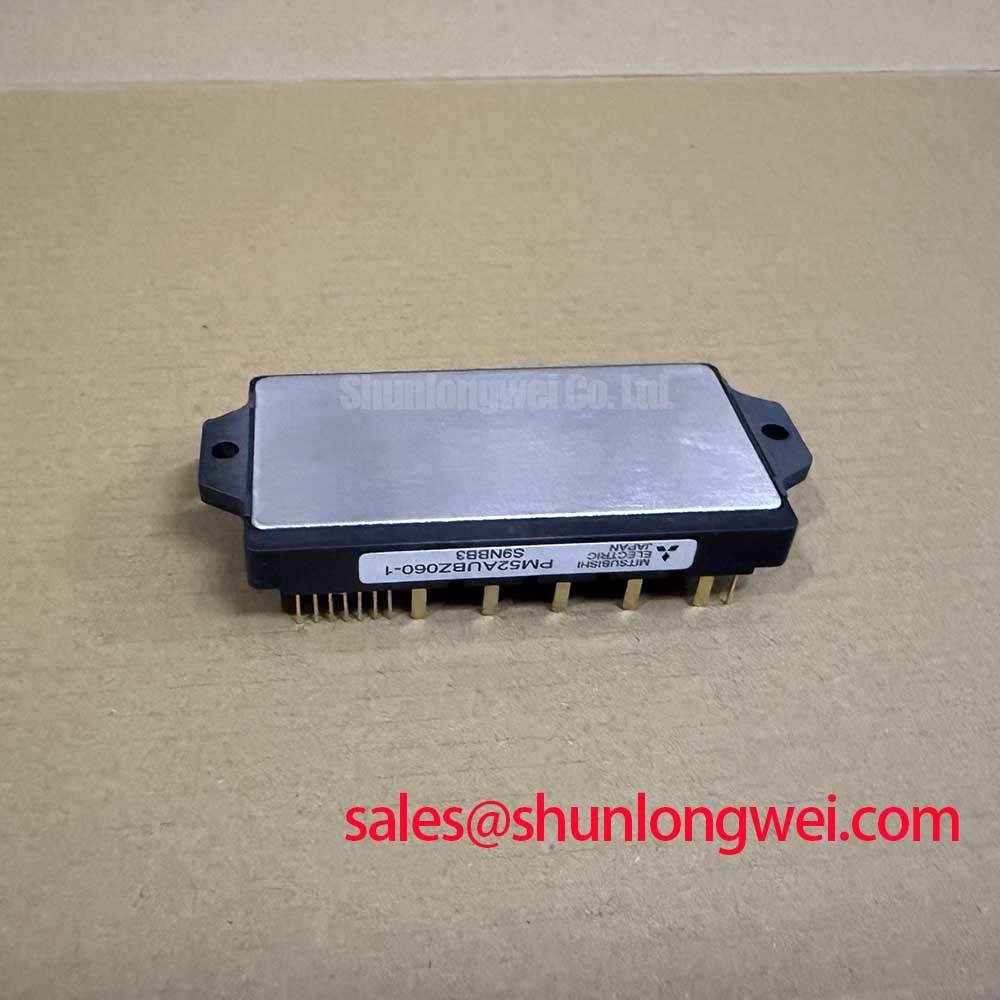
The PM52AUBZ060-1 is a Mitsubishi Electric intelligent power module rated at 600 V and 50 A under specified conditions. Its official circuit arrangement is a 6-in-1 three-phase inverter in one transfer-mold package, providing the complete switching bridge required by a three-phase motor inverter. Official protection functions include short-circuit protection and over-temperature protection, with integrated sensing intended to initiate shutdown when a protection condition is detected. The module is specified for 2500 Vrms AC insulation for 1 minute.
| Technical Item | Official Specification |
|---|---|
| Manufacturer | Mitsubishi Electric |
| Module model | PM52AUBZ060-1 |
| Voltage rating | 600 V |
| Current rating | 50 A under specified conditions |
| Inverter circuit | 6-in-1 three-phase bridge |
| Protection logic | Short-circuit and over-temperature protection |
| Isolation rating | 2500 Vrms AC for 1 minute |
| Package format | Transfer-mold package |
For electric material-handling equipment and forklift traction controllers, the module’s suitability must be assessed against the original inverter’s DC-link voltage, motor current profile, cooling arrangement, terminal arrangement, driver interface, and protection behavior. The 600 V and 50 A figures are official datasheet specifications under their applicable conditions, not a statement that the module can be installed in every 200 V or 400 V class traction controller without system verification.
Transient Dynamics & Electrical Design: High-Frequency Common-Mode Bearing Current on PM52AUBZ060-1
Before replacing a failed inverter module, inspect the motor cable route and confirm whether the service issue emerged after cable repair, cable extension, motor replacement, or an enclosure layout change. A three-phase inverter does not see a long motor lead as a simple wire at switching edges. The cable behaves as a transmission path, and a mismatch between cable impedance and motor impedance can reflect energy back toward the motor terminals or inverter output.
For the PM52AUBZ060-1, the first electrical boundary to preserve is its official 600 V rating. A reflected motor-terminal voltage can rise substantially above the local DC-link level under particular cable, load, and switching conditions. The commonly discussed possibility of a reflected peak approaching twice the DC-link voltage is a Design Consideration, not an official PM52AUBZ060-1 switching guarantee. It depends on cable length, cable construction, motor winding behavior, switching transition speed, termination conditions, and the actual inverter bus voltage.
Use an appropriately rated differential measurement method to compare the DC bus, the module output, and the motor-end waveform during the operating condition associated with the fault. A waveform with ringing, repeated reflected peaks, or unusually high common-mode movement should be investigated alongside cable routing, motor grounding, and the physical separation between power conductors and low-level control wiring. Do not infer a single cause from motor bearing noise, insulation alarms, or intermittent over-current trips; each may have several electrical or mechanical contributors.
An output choke or dv/dt filter can be evaluated where the measured cable and motor behavior warrants it. This is an Engineering Recommendation: select and validate the filter against the actual motor current, switching frequency, temperature, insulation system, and control-loop behavior. The system engineer should confirm that the added impedance does not create unacceptable motor-control response or a new resonant condition.
Maintain intended creepage and clearance paths around high-voltage terminals, especially after field wiring work. Keep motor output conductors physically organized and avoid routing them beside signal leads that carry protection, command, or sensing information. The PM52AUBZ060-1’s 2500 Vrms AC for 1 minute isolation rating is an Official Datasheet Specification for the module; it does not establish the insulation rating of cable glands, PCB assemblies, connectors, heatsinks, or the complete traction controller.
Where a forklift controller also communicates with display or touch-control electronics, digital interfaces need their own routing and grounding review. An I2C bus is a separate low-voltage communication interface and should not be treated as evidence of power-stage immunity. Verify its signal integrity independently when common-mode noise is suspected.
PM52AUBZ060-1 Circuit Protection & Reliability: Calibrating High-Frequency Commutation Loop Inductance
During a bench repair, start by comparing the replacement module’s physical terminal layout and control connection arrangement with the original assembly before applying power. The PM52AUBZ060-1 combines six inverter switches into one package, so each phase connection and DC-bus connection participates in the commutation path. A misplaced busbar, loose terminal, damaged laminated connection, or changed capacitor position can alter the switching loop even though the module model is correct.
The underlying electrical relationship is straightforward: at turn-off, the peak voltage includes the DC-link voltage plus a parasitic-inductance contribution that rises with switching-current change rate. This is an Engineering Calculation principle expressed as Vpeak = VDC + Lsigma multiplied by di/dt. It explains why the geometry of bus conductors, DC-link capacitors, and module terminals matters, but it does not provide a universal numerical layout prescription for this module.
As a Design Consideration, minimize the high-current commutation loop area to suppress inductive overshoot. Symmetrical planar busbar geometry can be evaluated where the original controller architecture supports it. Keep the DC-link capacitor connection physically close to the inverter current loop and verify the result with switching measurements under the real load condition. Snubber-capacitor selection should likewise be established by measured ringing frequency, peak voltage, thermal loading, and control behavior, then confirmed at system level.
The internal short-circuit and over-temperature protections are official module functions, but they should be treated as protective responses rather than as normal operating controls. A repeated trip requires inspection of motor leads, phase-to-phase faults, output load condition, DC-link stability, cooling contact, and driver commands. Record the observed waveform and controller event history before changing multiple variables at once. That preserves useful fault evidence and prevents a repair from becoming an untraceable sequence of adjustments.
Heat removal depends on the complete mechanical stack rather than the module alone. The mounting face should be clean, flat, and free of raised residue. Apply thermal interface material according to the controller or material supplier’s documented process, then tighten fasteners progressively in a cross pattern so the mounting pressure is distributed consistently. The exact thermal-material thickness, fastener type, and torque are system-determined unless stated in the original equipment documentation.
Field Alert: Disconnect, lock out, and verify DC-link discharge before moving inverter busbars or control connectors, because stored energy and an unintended reconnection can damage the module and surrounding drive electronics.
When evaluating a different power module, do not treat current rating alone as proof of compatibility. For example, CM300DXDX1-24A is a separate module that requires independent review of voltage class, current capability, topology, package dimensions, terminal positions, driver requirements, protection behavior, thermal interface, and controller layout. It is not a direct replacement claim for PM52AUBZ060-1.
In controllers that use a distinct rectifier stage ahead of the DC link, a device such as CM100DY-12E may be reviewed as a complementary rectifier-stage component. The inverter module and rectifier stage serve different circuit functions, so their replacement decisions should remain separate and based on the original schematic and hardware configuration.
Transient Dynamics & Electrical Design: Dynamic Gate Impedance Control for Robust Operation on PM52AUBZ060-1
The PM52AUBZ060-1 is an intelligent power module, and the original controller’s drive and protection interface should be preserved. Do not assume undocumented gate-drive voltages, gate resistor values, auxiliary-emitter arrangements, or active-clamp circuitry from the module’s voltage and current ratings. The system integrator should verify the control-terminal requirements from the original controller documentation and the applicable Mitsubishi Electric documentation before modifying the driver board.
Cross-conduction can occur when a switching transition causes an unintended turn-on in the opposite device path. High dv/dt, shared control-return impedance, coupling between power and control conductors, incorrect dead-time management, and a damaged driver channel can all contribute. A low-impedance active Miller clamp is a possible Design Consideration for a driver architecture that supports it, but its presence, implementation, and validation must be determined by the controller design.
When a controller has repeated protection events after module replacement, inspect the gate-driver supply rails, command timing, control-return path, and connector seating before changing component values. Measure the relevant control signals against a known-good channel or documented reference condition with appropriate isolation. A distorted turn-off waveform may indicate coupling or layout interaction, while an apparently clean gate command does not on its own rule out a power-loop or load-side problem.
Keep sensitive control paths separated from the phase-output and DC-bus conductors where the enclosure allows. The practical aim is to reduce noise coupling into drive, sensing, and fault inputs. The required spacing, shielding method, routing layer, and return path are Design Considerations that must be validated in the completed inverter, including its motor cable and enclosure.
Protection coordination is especially important in repair work. The PM52AUBZ060-1 includes official short-circuit and over-temperature protection functions, but upstream fuses, contactors, controller firmware, current sensing, precharge hardware, and motor protection remain system responsibilities. A functioning module protection feature cannot demonstrate that the complete forklift traction inverter has appropriate fault coordination or electromagnetic compatibility.
Benchtop Waveform Tuning: Mitigating Stress via DC-Bus Operating Voltage Headroom Derating on PM52AUBZ060-1
Confirm the actual DC-bus operating range from the original traction controller documentation and measure it during charging, regenerative braking, acceleration, and fault recovery. The PM52AUBZ060-1 is officially rated at 600 V, while the permissible operating voltage for a particular controller is determined by the entire system: capacitor rating, brake chopper operation, battery or supply behavior, contactor control, motor load, cable-induced overshoot, and the original equipment protection strategy.
Voltage headroom is an Engineering Recommendation, not a fixed percentage that can be assigned from the module nameplate. Designers should verify peak switching voltage against the DC-link voltage under representative current and temperature conditions. This process should include the highest credible bus condition and the motor-cable arrangement used in the equipment. A bench measurement taken only at no load may not represent the stress observed during traction acceleration or regenerative transitions.
High-altitude operation and neutron-related single-event behavior are high-risk reliability topics. No PM52AUBZ060-1-specific field failure-in-time value, single-event burnout rate, altitude derating curve, or service-life figure is stated here because no applicable official source has been provided. As a Design Consideration, equipment intended for unusual altitude or mission conditions should be evaluated using the original manufacturer documentation and the relevant system-level qualification process rather than assumptions derived from general component discussions.
For waveform tuning, change one verified variable at a time and preserve before-and-after captures of the DC-link and phase-output behavior. Check that probes, grounding, bandwidth, and measurement locations do not create misleading ringing. Review capacitor condition, busbar contact pressure, motor-cable routing, output filtering, and control timing as a connected set of influences. This gives maintenance teams a defensible basis for deciding whether the issue lies in the module, drive board, bus assembly, motor cable, or load.
For broader context on switching loss, industrial-drive stress factors, and device-selection questions, consult Unlocking Efficiency in Industrial Drives. That technical discussion should be used as background only; it does not replace verification against the PM52AUBZ060-1 official ratings and the original traction-controller design.