Content last revised on September 16, 2026
PM52AUBW060 Thermal and Electrical Optimization: Practical Tuning of Static and Dynamic Current Distribution
Before connecting a replacement unit, verify the equipment nameplate and DC bus arrangement against the PM52AUBW060 ratings, then inspect the power terminals, control connector, heatsink contact area, and surrounding snubber or surge suppression parts with the system fully isolated.
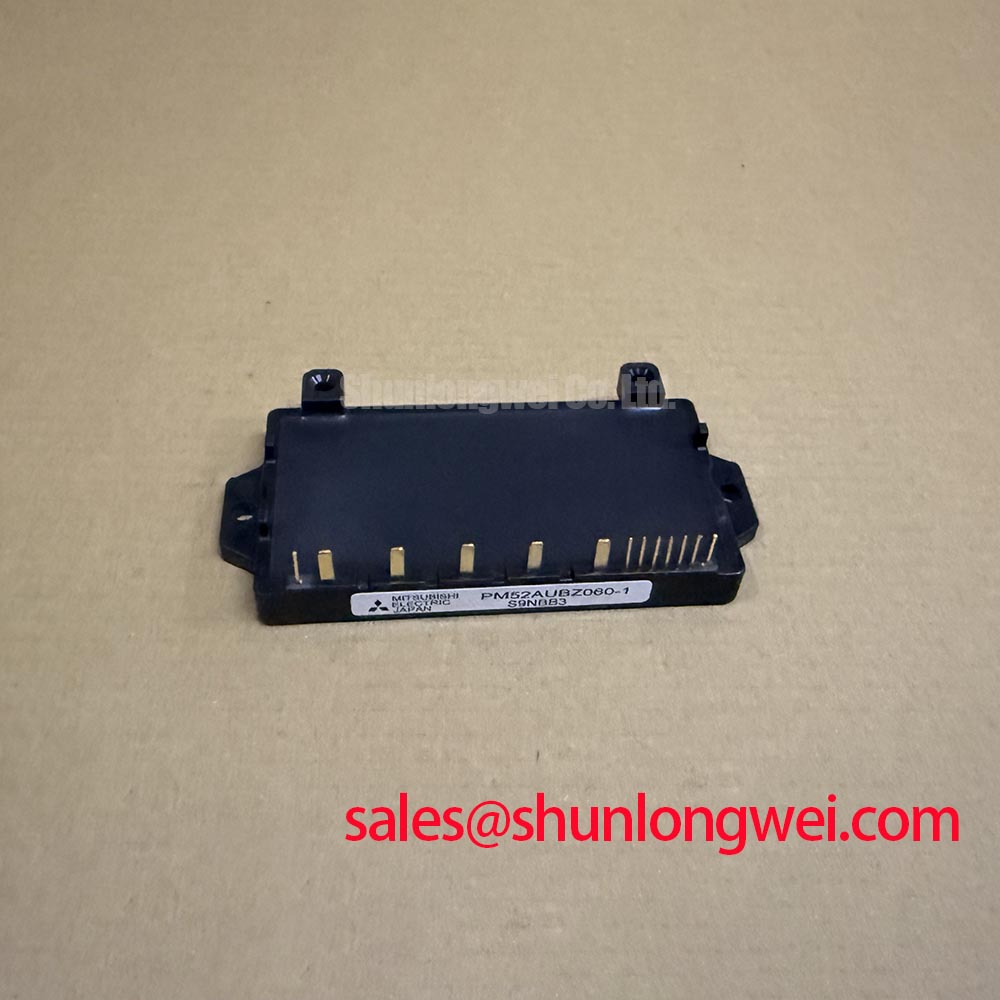
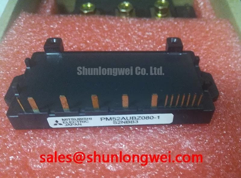
The PM52AUBW060 is a Mitsubishi Electric intelligent power module integrating a converter, inverter, and brake power stage in one package. Its official ratings identify a 600 V collector emitter voltage, 50 A inverter collector current at Tc = 25°C, 800 V converter repetitive peak reverse voltage, and a 15 V typical control supply. These values establish the electrical identity of the module and should be checked against the original drive documentation before any repair or redesign decision.
| Official Specification | Rated Value | Engineering Significance |
|---|---|---|
| Collector Emitter Voltage | 600 V | Official datasheet specification for the inverter switching voltage rating. |
| Inverter Collector Current | 50 A at Tc = 25°C | Official datasheet specification defining inverter load capability under the stated case temperature condition. |
| Converter Repetitive Peak Reverse Voltage | 800 V | Official datasheet specification for the converter section's repetitive reverse-voltage rating. |
| Control Supply Voltage | 15 V typical | Official datasheet specification for the module control supply. |
| Integrated Functions | Converter, inverter, brake | Official functional integration of the front end, motor power stage, and braking function. |
For industrial inverter welder and medium frequency induction heating equipment, these ratings support an initial compatibility review only. The system integrator should confirm the original control board pin assignment, DC bus condition, cooling interface, braking connection, and protection logic from the equipment documentation. A module with the same broad voltage class is not automatically electrically or mechanically interchangeable.
When investigating repeated inverter failure, begin with a cold system check of the DC bus, motor or work coil connection, heatsink flatness, and power terminal fastening. A failed module can be accompanied by external damage in the gate drive board, rectifier section, brake path, or bus capacitor bank. Replacing only the power module without checking these connected circuits can leave the underlying stress condition unchanged.
The 50 A inverter collector current at Tc = 25°C is an official rating, not a guaranteed current capability for every enclosure temperature, switching frequency, cooling path, or load waveform. Actual current distribution in a multiphase inverter depends on the control sequence, device temperature, commutation conditions, and the physical symmetry of the power and drive paths. The positive temperature behavior commonly associated with IGBT conduction characteristics can assist steady state sharing in parallel arrangements, but it does not remove the need to validate transient sharing during switching.
Design Consideration: Keep corresponding power paths and control return paths as geometrically similar as practical when evaluating parallel or closely coupled switching branches. Unequal loop inductance can cause one path to turn on or turn off differently from another, producing unequal switching stress even when steady state current appears balanced. Engineers should confirm this with synchronized current and voltage measurements under representative operating conditions.
For a repair bench, compare phase output behavior against the original healthy circuit path where available. Examine whether the control supply remains stable near the module, whether command pulses are present at the correct time, and whether bus ripple increases during load demand. An oscilloscope measurement using an appropriate differential method can show whether overshoot, ringing, or timing asymmetry is associated with the module location, the gate drive circuit, or the surrounding bus structure.
Thermal contact also affects electrical behavior. The mounting surface should be clean, flat, and free of trapped debris before applying the interface material specified by the equipment manufacturer. The original heatsink airflow, coolant route, and fan status should be verified because a restricted cooling path can elevate case temperature and alter the available operating margin. Pro Tip: Measure switching waveforms at the module connection points after any busbar or driver-board repair, because a visually correct assembly can still contain an inductive return path that creates harmful turn off overshoot.
For sourcing evaluation where the original integrated topology cannot be retained, the CM300DXDX1-24A is a separate Mitsubishi Electric power module reference that engineers may review as part of a wider system assessment. Its circuit arrangement, package interface, control requirements, voltage rating, and current rating must be independently compared with the failed assembly. It should not be treated as a direct replacement for PM52AUBW060 without a documented redesign review.
PM52AUBW060 Fault-Clearing Dynamics and Desaturation: Practical Tuning
Short circuit protection must be considered at the complete equipment level. The supplied official PM52AUBW060 parameters identify voltage, current, control supply, and integrated power functions, but they do not establish a short-circuit withstand time, desaturation threshold, fault response delay, or soft turn off profile. These values should not be assigned to this model without the applicable manufacturer documentation for the specific control arrangement.
In a drive using external or board level gate control, desaturation monitoring is commonly used as a Design Consideration to identify an abnormal rise in collector emitter voltage while a switching device is commanded on. A controller may distinguish between a hard fault condition and a developing overcurrent event through its protection architecture. The relevant response is determined by the controller, sensing path, isolation method, driver capability, bus inductance, and load behavior rather than by the inverter current rating alone.
Protection timing deserves direct bench verification because a very rapid current rise can produce damaging energy before a slow controller decision is completed. The requested protection response should be evaluated with a controlled test arrangement and appropriate safety procedures. Engineers should capture command state, collector emitter voltage, phase current, and DC bus voltage together. A voltage rise during an on command may indicate a protection event, a drive supply issue, an incomplete gate command, excessive load demand, or a damaged power path. The waveform sequence is more useful than a single static measurement.
A two stage turn off approach is often considered where an immediate removal of drive could combine with stray inductance to create a substantial voltage excursion. Engineering Recommendation: Use a controlled fault response strategy that first limits the switching transition and then establishes the required off state, subject to validation of peak voltage, current decay, and controller recovery behavior in the actual equipment. The final timing and drive levels are system determined and should be verified against the 600 V inverter voltage rating during switching tests.
Control signal isolation also deserves attention. In high noise inverter layouts, the gate drive command path must retain its intended logic state while the power stage switches. Engineers assessing isolated command paths can review the operating principle of galvanically isolated optical couplers for gate drive signals. This reference explains the isolation concept, but does not establish a PM52AUBW060 specific isolation rating or control circuit specification.
A negative gate bias, where used in an external gate drive system, is a Design Consideration for maintaining turn off immunity against Miller induced coupling. It is not an official PM52AUBW060 requirement in the supplied specification set. The system integrator should verify whether the original control board uses this technique and whether its driver, isolation barrier, and module interface were designed for it before changing any gate bias arrangement.
Transient Dynamics & Electrical Design: Long Motor Lead Reflected Wave Voltage on PM52AUBW060
Long cable connections between an inverter output and a motor, transformer, or induction heating load can behave as transmission paths rather than simple conductors during fast switching. A mismatch between cable impedance and load impedance can reflect part of the switching edge back toward the inverter terminals. Under unfavorable conditions, reflected wave voltage can approach twice the DC bus voltage at the remote load connection. This is a general transmission line effect, not a PM52AUBW060 guaranteed operating characteristic.
For equipment using the PM52AUBW060, the first practical task is to document the actual cable route, conductor construction, shield termination, output contactor state, and load connection quality. A loose output terminal, damaged insulation, unbalanced cable routing, or a disconnected load element may alter the observed waveform. Test measurements should be made with instrumentation suitable for the expected common mode movement and voltage level, and they should be compared with DC bus voltage and control timing.
Design Consideration: Minimize the area of high current commutation loops and maintain a short, direct DC link connection where practical to suppress inductive overshoot during switching. The engineer should validate peak collector emitter voltage against the DC bus condition and the 600 V official module voltage rating using double pulse or representative load tests. The required busbar arrangement, output choke, and dv/dt filter characteristics are determined by cable length, switching behavior, load impedance, enclosure layout, and control strategy.
Output filtering can be evaluated when measurements indicate unacceptable voltage reflection or excessive ringing at the load. A reactor or dv/dt filter may change both the voltage edge and the load current response, so its selection should be assessed with the actual machine operating sequence rather than by a generic component value. In induction heating systems, the interaction of the inverter, resonant network, and work coil needs particular care because a change in cable or passive network characteristics can shift the observed current and voltage relationship.
Engineers researching switching topologies that influence these test conditions can consult Resonant Topologies in Home Appliances. The article can provide context for topology comparison, while the PM52AUBW060 integration decision still requires verification of the original converter, inverter, and brake connections.
For three phase motor output analysis, modulation behavior also influences the phase voltage sequence and common mode activity. The principles behind Space Vector Modulation in three phase motor inverters can help engineers interpret command and output waveforms. It does not confirm that a particular PM52AUBW060 application uses SVM; the equipment controller firmware must be checked directly.
Benchtop Waveform Tuning: Mitigating Stress via Insulation Barrier Integrity on PM52AUBW060
Before applying power after a repair, inspect the separation between control wiring and power conductors, the condition of the driver board insulation features, and the routing of measurement leads. The supplied official specification does not state reinforced isolation capability, an isolation test voltage, or common mode transient immunity for PM52AUBW060. Claims of a reinforced barrier above a particular voltage or a defined CMTI value should therefore be verified from the relevant module and driver documentation rather than assumed from the IPM designation.
Common mode transients can couple into command circuits through isolation components, supply returns, measurement wiring, and parasitic capacitance between the power stage and control board. A spurious switching command may be associated with common mode disturbance, but it may also involve control firmware, gate driver supply behavior, grounding layout, connector contact condition, or probing technique. Engineers should inspect the relationship between the controller command, isolated output, local control supply, and phase voltage before assigning a cause.
Engineering Recommendation: Separate sensitive control returns from high di/dt power return paths where the existing equipment architecture permits, using the original reference scheme as the starting point. The purpose is to reduce ground bounce and false gate triggering during commutation. Any layout revision should be tested with realistic load transitions, including startup, reversal where applicable, braking events, and maximum expected bus disturbance.
The integrated converter and brake functions require attention during this work. The 800 V converter repetitive peak reverse voltage is an official parameter for the converter section, while the brake circuit connection and external energy handling path must be checked against the original machine schematic. If a braking resistor, clamp network, or metal oxide varistor is present, inspect its connection and condition as part of the DC bus overvoltage investigation. A MOV network is a system level surge coordination element; its voltage selection and energy capability cannot be derived from PM52AUBW060 ratings alone.
Control supply stability should be confirmed at the module interface under both idle and switching conditions. The specified 15 V typical control supply provides an important reference, but the system integrator should verify startup sequencing, supply ripple, brownout behavior, and driver enable logic using the original equipment documentation. During bench tuning, record the waveform evidence before altering damping, filtering, isolation components, or protection thresholds. This preserves a traceable basis for deciding whether the issue originates in the module, drive board, power loop, or connected load.