

Content last revised on September 14, 2026
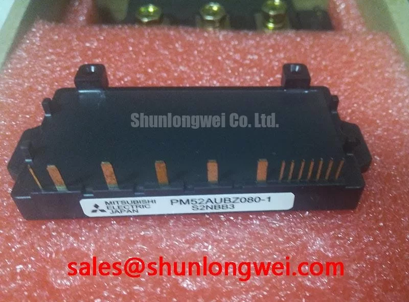
PM52AUBZ080 Specifications and Application Boundaries
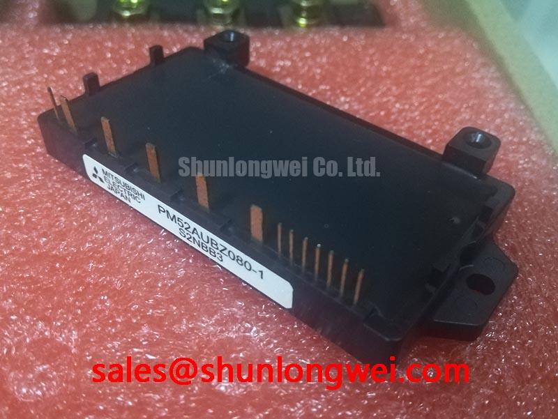
Before fitting PM52AUBZ080, verify the equipment nameplate boundaries and inspect the isolated heatsink interface for flatness, contamination, and aged thermal material while the system is safely de-energized. This Mitsubishi Electric intelligent power module is specified with a maximum peak output voltage of 800 V, an input current rating of 20 A rms, and a 25 A one minute overload rating. These Official Datasheet Specifications define the electrical boundary that maintenance teams should compare with the original power stage before commissioning a repaired inverter front end.
| Official Specification | Rated Value or Condition | Integration Relevance |
|---|---|---|
| Peak output voltage, Vo | 800 V maximum | Defines the stated output-voltage boundary for 200 V class active PFC boost topologies. |
| Input current, Ii | 20 A rms | Defines the stated input-current rating under its specified conditions. |
| Overload input current | 25 A for 1 minute | Provides a specified short duration overload condition for equipment level assessment. |
| Isolation voltage, Viso | 2500 Vrms AC for 1 minute | Specifies isolation between internal high voltage silicon and the grounded heatsink. |
| Switching frequency, fSW | 20 kHz typical | Supports ultrasonic range switching evaluation and compact magnetic component selection. |
| Case operating temperature, Tc | −20 °C to +100 °C | States the permitted case temperature operating range. |
For industrial inverter welders and medium frequency induction heating power supplies, the module should be assessed as part of the complete rectifier, DC link, control supply, cooling path, and protective control system. The published values do not independently establish suitability for a particular machine duty cycle, incoming line condition, or load profile. System integrators should verify the original circuit documentation, terminal arrangement, control sequence, and measured switching waveforms before applying power.
PM52AUBZ080 Operational Boundaries: Evaluating Thermal Capacitance vs Heat Sink Limits
Start thermal assessment at the actual module mounting plane rather than at the cabinet air inlet. The −20 °C to +100 °C Tc operating range is an Official Datasheet Specification for case temperature, not a statement of the internal junction temperature under every load condition. A clean heatsink can still produce an unfavorable module case temperature if contact pressure, thermal interface material, airflow direction, or recirculated exhaust air has changed since the machine was installed.
For pulsed industrial loads, the thermal response is not represented by a single steady state temperature reading. Junction temperature rises through multiple thermal time constants associated with the semiconductor assembly, package, interface material, and heatsink. Engineering Calculation requires the manufacturer supplied transient thermal impedance curves and the operating loss waveform. As those curves and device loss parameters are not provided in the available official specifications for this page, a credible peak junction temperature calculation should not be substituted with assumed values.
A practical maintenance method is to record heatsink temperature at repeatable production conditions, compare it with the historical commissioning baseline where available, and check whether cooling performance changes during sustained output rather than only during idle operation. A rising case temperature can reflect several conditions, including blocked fins, degraded fan performance, hardened interface material, uneven mounting contact, altered ambient temperature, or a power stage operating outside its original switching conditions. It does not by itself identify one failed part.
⚠️ Maintenance Note: Periodically monitor contact temperature rise and confirm that the cooling air path remains free of dust accumulation before a thermal alarm develops into an unplanned shutdown.
Design Consideration: heatsink flatness, interface coverage, mounting pressure distribution, enclosure airflow, and condensation control should be reviewed together. In cold and humid industrial locations, moisture management matters during both shutdown and restart because condensation around bus connections and control circuitry can cause intermittent faults that resemble thermal or gate drive problems. Allow the enclosure environment to stabilize before applying high voltage after prolonged cold storage.
The 2500 Vrms AC for 1 minute isolation voltage is an Official Datasheet Specification that addresses the module isolation barrier under its stated test condition. It should not be treated as an equipment level insulation coordination claim. The required clearance, creepage, enclosure construction, protective earth arrangement, and compliance assessment remain dependent on the complete machine design.
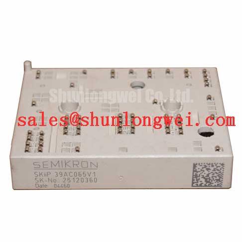
Engineers comparing a repair option with another power module family can use SKIIP37AC12T4V1 as a neutral reference point for reviewing published ratings, package interface, topology, control requirements, and cooling constraints. A matching voltage number alone does not establish direct interchangeability.
Benchtop Waveform Tuning: Mitigating Stress via Planar Symmetrical Busbar Geometry on PM52AUBZ080
Before connecting the DC link, compare each power terminal and control terminal against the original equipment schematic and the module documentation. Do not infer a terminal function from package position or from a visually similar module. Confirm connector keying, conductor routing, protective earth continuity, and isolation from the grounded heatsink with the equipment de-energized.
At switching transitions, the voltage appearing across a power semiconductor is influenced by DC link voltage and by the product of loop inductance and the rate of current change. This Engineering Principle explains why a long or asymmetric current path can produce overshoot, ringing, and uneven stress even when the measured steady state DC bus remains within the 800 V maximum Vo rating. The design objective is to minimize the commutation loop inductance, especially between the DC link capacitor, module power terminals, and return path, then verify peak switching voltage under representative load conditions.
Planar, closely coupled busbar geometry is often evaluated where the mechanical layout allows it because adjacent outgoing and return paths reduce the loop area. This is a Design Consideration, not a module specific construction instruction. The required conductor dimensions, capacitor placement, snubber arrangement, and fastening design are determined by the machine current waveform, fault energy, insulation system, vibration environment, and measured voltage peaks.
When ringing appears on a measured waveform, inspect the measurement method before changing the power stage. Probe grounding, probe bandwidth, sensor position, and common mode noise can distort a fast switching observation. Compare the signal against a known stable measurement path where possible. If overshoot remains confirmed, inspect DC link capacitor connections, busbar symmetry, terminal tightness, and the physical distance between the capacitor and power loop before considering a circuit level damping change.
The stated 20 kHz typical switching frequency provides an official reference for application evaluation. It should not be interpreted as authorization to operate any surrounding magnetic components, snubbers, control supplies, or load network at an arbitrary frequency. In inverter welding and induction heating equipment, switching frequency selection remains linked to the complete resonant or conversion topology and the verified thermal behavior of the assembled machine.
Where a related driver circuit uses a bootstrap supply, capacitor recharge time, diode recovery behavior, and supply stability should be checked across expected operating states. Mitsubishi Electric provides useful general driver context in its DIPIPM™ bootstrap circuit design note. That reference is educational support for associated driver design and does not establish an internal feature or pin function for PM52AUBZ080.
Preventing Spurious Faults: Thermal Cycling Margins and Braking Path Checks for PM52AUBZ080
In equipment that includes a motor deceleration function, evaluate the braking path as a system function rather than attributing all DC link alarms to the power module. Mechanical load inertia can return energy to the DC link during deceleration. Whether that energy is handled by a braking transistor, resistor network, regenerative circuit, or control strategy depends on the original equipment topology. PM52AUBZ080 official ratings listed here do not specify an internal braking circuit or braking resistor capability, so no such feature should be assumed.
During a recurring fault investigation, record the operating state that precedes the trip. Useful observations include whether the event occurs during acceleration, deceleration, load changes, high cabinet temperature, or a particular production sequence. Inspect resistor connections, thermal protection wiring, contactor operation, and DC link behavior with appropriately rated equipment. A trip under deceleration may indicate an energy handling or control timing issue, but requires waveform and circuit evidence before replacing any power component.
Thermal cycling deserves equal attention during planned maintenance. Repeated heating and cooling can loosen terminal hardware, degrade thermal interface material, and expose airflow deficiencies gradually. Recheck accessible connections according to the equipment manufacturer’s maintenance procedure. Do not use a generalized torque value as a substitute for the original module, busbar, or equipment documentation.
Long output conductors in motor driven machinery can also alter observed switching stress through transmission line reflections. Depending on cable length, motor impedance, termination conditions, and switching edge behavior, reflected voltage can raise the stress at the motor terminals. Design Consideration: evaluate the cable path, output filtering approach, and measured motor terminal waveform as a complete system. It is not valid to state a fixed reflection multiplier without the actual cable and load conditions.
For broader guidance on selecting and maintaining power semiconductors at the equipment level, the Power Electronics Masterclass discusses system reliability considerations that should be reviewed alongside the original machine documentation. It should not replace manufacturer specific qualification data for a particular module.
High altitude, cosmic radiation exposure, single event burnout behavior, equipment lifetime, and failure rate are high consequence subjects. No numerical prediction for these conditions is made here because the stated official information does not provide the necessary qualification data, environmental model, or application profile. Designers responsible for those conditions should obtain relevant manufacturer documentation and perform an application specific risk assessment.
Field Diagnostics & Commissioning: Isolated DC DC Power Supply Checks for PM52AUBZ080 Topologies
Commission the low voltage control supply and protective functions before allowing normal power conversion. Verify the control supply sequence, supply stability, commanded enable state, interlock chain, and fault reporting path with the original schematic. The module’s 2500 Vrms AC for 1 minute isolation specification does not state the performance of an external isolated DC DC converter, gate driver, current sensor, communications interface, or their common mode transient immunity.
Design Consideration: maintain the intended separation between high voltage power conductors and low voltage control wiring, route sensitive feedback paths away from high current switching loops, and confirm that the protective earth connection follows the original equipment design. These measures can reduce unwanted coupling, but the resulting noise immunity must be verified on the assembled equipment with appropriate measurements.
Spurious drive commands can arise from supply disturbance, reference movement, harness damage, connector contamination, inadequate shielding, controller logic, or measurement error. Begin with an objective check of the commanded signal and its return reference at the driver interface. Then compare the control supply behavior and power waveform against a known good operating condition if one is available. Replacing the module before separating a control path issue from a power path issue can leave the original fault unresolved.
For circuits using transformer isolated energy transfer, the relationship between switching, stored magnetic energy, and isolated output behavior is described in this technical reference on flyback converter operation and transformer isolation. The reference explains general topology physics only; it does not identify the topology or supply requirements of PM52AUBZ080.
After repair, commission with the equipment’s documented protection sequence active. Observe cooling airflow, heatsink temperature trend, terminal condition, DC link behavior, and fault response through controlled operating states. The final acceptance decision should be based on measured machine performance within the original electrical and thermal design limits.