Content last revised on September 18, 2026
MIG20J503H Thermal-Electrical Optimization: Galvanic Gate Drive Isolation and Practical Tuning
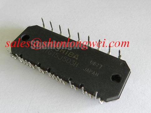
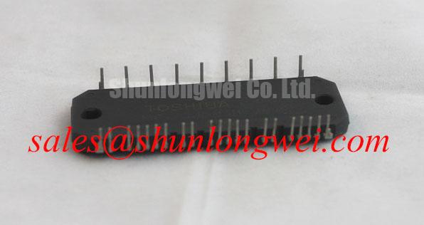
With the drive fully isolated from its DC link and control supply, begin incoming inspection of the MIG20J503H by checking the module marking, terminal condition, and cold-state resistance relationships against the original inverter schematic. This Toshiba IGBT Module has a specified voltage rating of 600V and a specified current rating of 20A; these values define the electrical identity that must match the failed position before any replacement decision is made.
| Parameter | Specified Value | Classification |
|---|---|---|
| Product model | MIG20J503H | Official identification |
| Manufacturer | Toshiba | Official identification |
| Rated voltage | 600V | Official Specification |
| Rated current | 20A | Official Specification |
| Package form | Module | Official Specification |
For a heavy-duty variable frequency AC motor drive repair, these ratings should be compared with the original bill of materials, DC bus operating range, motor current demand, cooling arrangement, gate-driver circuit, and physical terminal layout. The supplied information does not establish the internal circuit topology, terminal assignment, insulation rating, switching characteristics, short-circuit capability, thermal resistance, or mounting dimensions. The system integrator should verify those details from the original equipment documentation and the applicable Toshiba documentation before energizing the inverter.
Before connecting a replacement MIG20J503H, trace every control connector and power terminal from the inverter drawing rather than relying on package appearance. A module can share a broadly similar outline with another power device while having a different terminal order or internal arrangement. With the unit removed from the circuit where practical, compare diode-mode readings between expected power terminals with readings from a known-good position or an approved reference unit. Gate terminals should not be treated as power terminals during this check, and meter polarity should be documented so later results can be compared consistently.
Galvanic isolation belongs to the gate-drive system, not to the published electrical rating of this module. Whether the installed driver has reinforced insulation, suitable common-mode transient immunity, or the required creepage and clearance depends on the drive-board design and its supporting components. This is a Design Consideration: inspect the isolation barrier, isolated supply return, gate-drive cable routing, and controller ground reference when unexplained switching commands appear on an otherwise valid control signal.
A false turn-on event can result from common-mode movement, coupling through a long gate path, poor return routing, damaged driver isolation, or an incorrect measurement reference. It should not be attributed to the module without evidence. Use an appropriately rated differential measurement method to observe the gate-emitter control signal and switching-node movement together. Compare the captured waveform with a known-good inverter phase where available, while keeping the test setup compatible with the equipment safety procedure.
Gate resistor selection, separate turn-on and turn-off paths, and any negative gate bias are system-dependent design choices. They are not confirmed factory settings for the MIG20J503H. Designers should minimize the gate-loop area to limit parasitic inductance, then verify switching overshoot, ringing, gate stability, and thermal behavior under the actual DC bus and motor load conditions. Useful gate-driver evaluation principles are discussed in Precision Gate Drive Design.
💡 Bench Tip: Record cold-state diode-mode and isolation readings before installation, and use ESD-controlled handling whenever the gate terminals are accessible.
Thermal integration also requires separation of fact from assumption. The official information identifies a module package but does not provide a junction temperature limit, baseplate construction, approved thermal interface material thickness, mounting torque, or heatsink flatness requirement. As an Engineering Recommendation, remove old thermal compound evenly, inspect the heatsink contact surface for debris or damage, and follow the original equipment manufacturer’s specified fastener pattern and torque. The system should then be commissioned with thermal observation appropriate to the application rather than assuming the replacement will reproduce prior operating temperature.
Field Diagnostics and Commissioning: Turn-Off Transients in MIG20J503H Topologies
During a variable frequency drive fault investigation, inspect the DC link, braking path, phase output cables, current sensing circuit, and motor insulation before assigning the event to the installed power module. A turn-off transient is influenced by the relationship between DC-link voltage, stray inductance, and the rate at which current changes. In practical terms, peak voltage rises above the DC bus when inductive energy is released during switching. The actual peak must be measured in the assembled inverter because busbar geometry, capacitor placement, probe technique, cable length, gate drive, and load current all affect the result.
This is a Design Consideration: keep the commutation loop compact between the DC-link capacitors and power terminals to suppress turn-off inductive overshoot. Symmetrical conductor paths can assist current sharing in multi-device arrangements, but suitability must be verified from the specific inverter layout and its measured switching waveforms. A snubber network, if present, should be assessed as part of the complete topology. Its value, voltage capability, loss, and physical placement are system-determined and should not be transferred from an unrelated drive.
Commissioning should begin at a controlled operating condition defined by the equipment procedure. Observe phase current balance, DC-link behavior, gate command timing, and temperature response while the motor is operated through the intended speed range. If a waveform indicates excessive ringing, investigate connection length, loose hardware, capacitor condition, gate-loop routing, measurement technique, and control-board references. A single waveform feature may have multiple contributing causes, so comparison against an equivalent healthy phase or known-good drive is more useful than relying on a universal threshold.
Where semiconductor fuses are used, their coordination must be reviewed against the equipment designer’s protection strategy. Fuse clearing behavior, fault current, upstream source impedance, contactor action, and controller response all influence whether a fault is isolated promptly. The 600V and 20A ratings of the MIG20J503H do not independently establish fuse selection or fault-energy withstand. Verify the fuse documentation and original inverter service data before returning the equipment to duty.
For applications requiring a different Toshiba module reference, MG75H6EL1 can be reviewed as a separate product record. It should not be considered mechanically, electrically, or functionally interchangeable with the MIG20J503H unless the original circuit topology, terminal arrangement, driver capability, cooling path, and all relevant manufacturer specifications have been verified.
Assembly Integrity and Layout Architecture: Environmental Limits for MIG20J503H
Inspect the module mounting plane and terminal hardware before installation. Uneven heatsink contact, contamination trapped beneath the module, damaged threads, poor busbar seating, or mechanically stressed control leads can affect electrical and thermal performance. The module’s published identification as a 600V, 20A Toshiba module does not provide a confirmed mounting-torque value, thermal interface requirement, vibration qualification, altitude limit, or insulation coordination rating. Those conditions must be recovered from the original equipment documentation or the applicable product documentation.
Power-module reliability discussions often refer to bond interconnections, substrate interfaces, terminals, encapsulation, and external joints. These mechanisms should not be assumed for the specific MIG20J503H without verified construction data. For general background on the role of electrical interconnects in semiconductor assembly, see Wire Bonding Metallurgical Reliability in Power Semiconductor Modules. The reference is useful context, not a product-specific construction disclosure or life prediction.
Altitude and terrestrial neutron exposure are high-risk reliability topics. No FIT rate, single-event burnout rate, altitude derating curve, service-life estimate, or DC-bus derating value is provided here because such figures require authoritative device qualification data and defined operating conditions. As a Design Consideration, equipment intended for elevated installations should be reviewed for enclosure cooling, insulation coordination, supply voltage conditions, transient exposure, and the manufacturer’s environmental requirements. The system owner should validate the application against qualified documentation rather than infer suitability from the basic voltage and current rating.
Power modules can be used within several inverter architectures, including bridge and chopper arrangements, but the actual internal configuration of the MIG20J503H must be confirmed before mapping it into a circuit. The broader relationship between power-module packaging and converter arrangements is described in Power Module Architecture and Topologies. During repair, the original schematic and terminal legend remain the primary references for determining how this specific module connects within the drive.
On a heavy-duty AC motor drive, regenerative braking should also be evaluated at system level. A braking chopper, braking resistor, DC-link capacitor bank, and control logic can each influence DC-link stress during deceleration. The MIG20J503H should not be assigned responsibility for a braking fault until resistor continuity, chopper command behavior, DC-link voltage response, and motor deceleration settings have been checked under controlled conditions.
Transient Dynamics and Electrical Design: Overcurrent Protection for MIG20J503H
Overcurrent protection must be treated as a coordinated inverter function. The available official data confirms the 600V rating and 20A rating, but it does not publish a short-circuit safe operating area, protection response time, desaturation threshold, allowable fault duration, or soft turn-off behavior for the MIG20J503H. It would therefore be inaccurate to state a specific short-circuit protection window or to prescribe a fixed protection setting for this model.
During commissioning, verify that the drive’s current sensing path, gate-driver fault output, controller interlock, fault latch, and shutdown sequence operate as intended. A suspected short-circuit event may stem from a motor cable fault, phase-to-phase load fault, output contactor issue, damaged current sensor, gate-drive overlap, control-command error, or DC-link disturbance. Disconnect and test the motor and output cable according to the equipment service procedure before repeatedly powering an inverter that has tripped.
Soft turn-off is often used in gate-drive systems to reduce inductive overvoltage when a high current must be interrupted. Whether it is implemented, and how it is configured, belongs to the original gate-driver design. An Engineering Recommendation is to confirm the shutdown waveform at the actual module terminals using suitable isolated instrumentation, then verify that peak voltage remains within the documented limits of every component in the commutation path. Do not modify gate-drive timing or protection thresholds solely from a bench observation without confirming controller behavior and fault-clearing coordination.
After repair, inspect terminal tightness, busbar alignment, control connector retention, heatsink contact, and protective-earth continuity as required by the machine procedure. Then document the MIG20J503H location, measured cold-state results, observed commissioning waveforms, and any replaced supporting parts. That record gives the next maintenance technician a defensible comparison point if the drive later develops another switching or protection-related fault.