Content last revised on September 10, 2026
Cosmic Ray Robustness: Voltage Derating Curves across 2000m-4000m Altitudes
In high-altitude wind turbine pitch and yaw converter installations—frequently situated in mountainous terrain between 2000m and 4000m above sea level—power semiconductors experience a marked increase in terrestrial cosmic ray neutron flux. The atmospheric neutron flux increases approximately by a factor of 10 at 3000m compared to sea-level baselines. High-energy neutrons colliding with the silicon lattice within the high-field drift region of an IGBT can trigger localized avalanche multiplication, leading to catastrophic Single Event Burnout (SEB) without prior thermal warning.
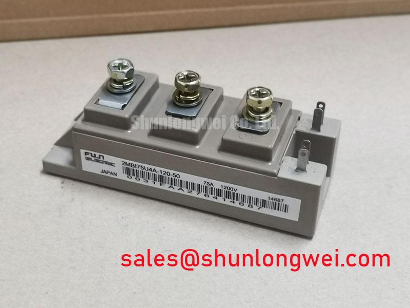
For the 2MBI75U4A-120, rated for a collector-emitter breakdown voltage VCES = 1200V and a continuous collector current IC = 75A (at TC = 80°C) / 100A (at TC = 25°C), operating margins must be evaluated using SEB failure rate modeling. The failure rate in Failure in Time (FIT, 1 FIT = 1 failure per 109 component hours) depends exponentially on the applied continuous DC-bus voltage (VDC) and the ambient altitude:
FIT(VDC, Altitude) = FIT0(VDC) × exp((Altitude [m]) / 780)
While standard low-altitude industrial inverters operating the Fuji Electric 2MBI75U4A-120 maintain continuous DC-bus levels between 750V and 800V, high-altitude wind power pitch systems must derate the steady-state DC link voltage. Engineering best practices established in the Fuji Electric V-Series IGBT Application Manual indicate that operating the DC link at 650V to 700V at 3000m altitude maintains an SEB failure rate under 100 FIT across the operational lifecycle.
| Operational Parameter | Specification Value | Engineering Significance |
|---|---|---|
| Collector-Emitter Voltage (VCES) | 1200V | Breakdown threshold defining cosmic ray & switching margins. |
| Continuous Collector Current (IC) | 75A (TC=80°C) / 100A (TC=25°C) | Continuous thermal current ceiling for yaw/pitch positioning. |
| Pulsed Collector Current (ICP) | 150A (TC=80°C) / 200A (TC=25°C) | 1 ms dynamic peak rating during motor torque surges. |
| Saturation Voltage (VCE(sat)) | 2.05V typ / 2.20V max | Conduction loss metric at IC = 75A, Tj = 25°C (chip terminals). |
| Maximum Power Dissipation (PC) | 400W per device | Maximum thermal transfer rate based on junction-to-case resistance Rth(j-c). |
| Isolation Voltage (Viso) | 2500V AC (1 min) | Baseplate-to-terminal dielectric safety isolation. |
Mitigating Hard Switching Transients via Active Desaturation Soft Shutdown
Wind turbine pitch actuators frequently encounter mechanical stalling due to severe aerodynamic gust loading, creating sudden phase-to-phase or phase-to-ground short-circuit conditions. Power stages driven by the 2MBI75U4A-120 dual-pack module are subject to Type-I (fault initiated prior to turn-on) and Type-II (fault occurring during the conduction phase) short-circuit regimes. According to power semiconductor standards, the Short-Circuit Safe Operating Area (SCSOA) defines a maximum short-circuit duration tsc ≤ 10 μs under conditions of VCC = 800V, VGE = ±15V, and starting junction temperature Tj ≤ 125°C.
During a short circuit, fault current surges to 4 to 6 times the rated IC (exceeding 400A). If the gate driver implements an instantaneous, hard turn-off at this current magnitude, the rapid rate of current decay (di/dt) across the parasitic circuit inductance (Lσ) induces an overvoltage transient:
Vpeak = VDC + Lσ × (di/dt)
This transient easily exceeds the 1200V VCES limit, causing avalanche breakdown and catastrophic collector-to-emitter failure. To mitigate this dynamic risk, active desaturation (DESAT) detection circuitry monitors the on-state voltage VCE. When VCE rises above the nominal VCE(sat) threshold of 2.05V–2.20V under full gate drive (VGE = +15V), a fault comparator triggers a Two-Stage Soft Turn-Off (2SSTO) sequence.
The 2SSTO circuit immediately steps down the gate-emitter voltage from +15V to an intermediate level (typically +8V) for 2 to 5 μs before pulling the gate to its negative off-state bias (-8V to -15V). This controlled gate discharge drastically reduces the di/dt slope during channel pinch-off, clamping the peak induced turn-off overvoltage well below the maximum silicon rating. Structural validation procedures for transient load boundaries are documented in the Field Engineer’s Handbook.
Suppressing C_res Induced Gate Voltage Spikes in High-Voltage Inverter Bridges
The dual-switch phase-leg configuration of the 2MBI75U4A-120 makes it susceptible to Miller capacitance cross-coupling during dynamic commutation. When the lower IGBT turns on, the collector-emitter voltage across the upper non-conducting IGBT transitions rapidly from near zero to the full DC-bus voltage, generating transient slew rates (dv/dt) exceeding 10 kV/μs.
This high dv/dt drives a displacement current idisp through the reverse transfer capacitance (Miller capacitance Cres = Cgc) of the off-state IGBT:
idisp = Cres × (dv/dt)
This displacement current flows through the internal gate resistance RG(int) and the external turn-off gate resistance RG(ext) toward the driver ground. The resulting voltage drop across these resistances induces a positive gate voltage bump:
ΔVGE = idisp × (RG(int) + RG(ext)) + Vneg
If ΔVGE crosses the gate threshold voltage VGE(th) (typically 5.5V to 6.5V for standard planar/trench silicon gates), parasitic cross-conduction (shoot-through) occurs, leading to excessive thermal stress and bridge short circuits. Standard drive designs utilize a dedicated negative gate bias (such as -8V or -15V within the rated VGES = ±20V limit) to ensure sufficient negative headroom.
To eliminate shoot-through risk without requiring complex bipolar auxiliary supplies, an active Miller clamp can be implemented. Once the gate voltage falls below approximately +2.0V during turn-off, a low-impedance internal MOSFET shorts the gate terminal directly to the emitter rail, bypassing RG(ext) and suppressing false turn-on spikes. For systems requiring higher continuous load handling alongside matching gate driver architectures, the related 2MBI450UE-120 offers an expanded 450A current rating.
DC-Bus Low-Inductance Laminated Busbar Design & Turn-Off Voltage Overshoot Suppression
Turn-off energy losses (Eoff) and peak voltage overshoots during inductive load switching are heavily governed by the total loop inductance of the DC-link layout. When switching inductive loads up to the pulsed current rating ICP = 150A / 200A, the total loop inductance includes the internal module packaging inductance, terminal connections, and the external busbar geometry.
To operate the 2MBI75U4A-120 safely within its 1200V collector-emitter boundary under dynamic turn-off speeds (di/dt ≥ 1.5 kA/μs), the total parasitic loop inductance Lσ must be maintained below 25 nH. Symmetrical planar laminated busbars utilizing wide copper sheets separated by thin dielectric insulation (e.g., 0.5 mm Nomex or Polyimide film) provide magnetic flux cancellation, minimizing stray inductance.
Direct mounting of high-frequency polypropylene film snubber capacitors (0.47 μF to 1.0 μF, low ESR/ESL) across the positive (P) and negative (N) terminals of the module provides a localized, low-impedance bypass path for high-frequency switching currents. This configuration clamps the turn-off voltage spike directly at the module pins. When designing multi-axis converter platforms incorporating complementary phase-leg subassemblies, utilizing devices like the 2MBI100NE-120 enables standardized mechanical clearance and consistent planar busbar routing across inverter channels, as detailed across the power portfolio at Fuji Electric Global Power Semiconductor Technologies.