

Content last revised on September 10, 2026
Isolated DC-DC Power Supply Sizing for High-Side Floating Gate Drivers
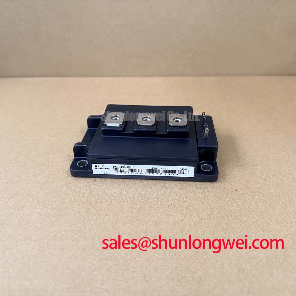
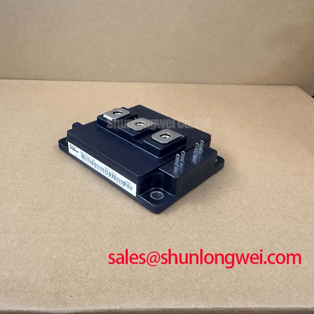
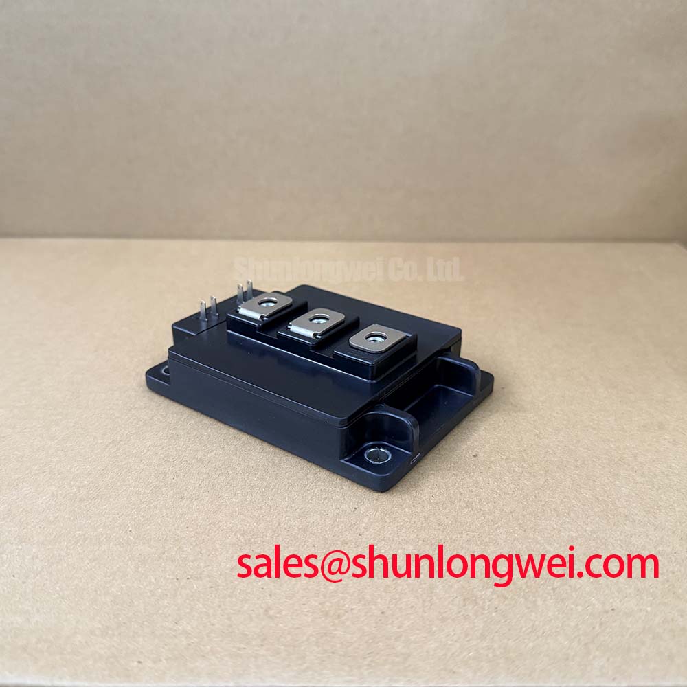
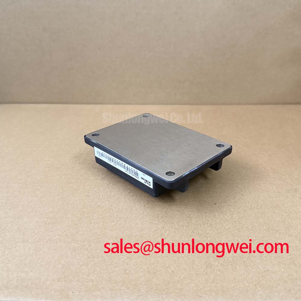
Deploying high-power converter stages in high-altitude (>3000m) wind turbine pitch and yaw drives introduces severe atmospheric stresses, notably reduced dielectric breakdown strength of air and accelerated thermal cycling. The Fuji Electric 2MBI450UE-120 dual IGBT module operates with a collector-emitter rating of VCES = 1200V (Official Datasheet Specification) and a continuous DC collector current of IC = 450A at 25°C (Official Datasheet Specification). Driving this dual-pack half-bridge topology in high-altitude environments requires robust galvanic isolation and carefully calculated gate driver power delivery.
Floating gate driver auxiliary supplies must deliver sufficient steady-state power without suffering thermal runaway or insulation breakdown under continuous high-voltage switching stress. The average output power required from the isolated DC-DC converter depends directly on the total gate charge and switching frequency. For the 2MBI450UE-120, the power delivery per channel is calculated via the relation Pgate = Vgate(total) × Qg × fsw (Engineering Calculation based on gate charge dynamics), where Vgate(total) represents the peak-to-peak gate voltage swing (typically +15V forward bias and -8V to -15V reverse cut-off bias), Qg is the total gate charge, and fsw is the converter switching frequency. In pitch motor positioning inverters operating at switching frequencies between 4 kHz and 8 kHz, sizing the auxiliary DC-DC converter for a continuous rating of at least 3W to 5W per channel provides adequate overhead (Design Consideration for industrial driver boards).
Common-mode transient immunity (CMTI) is critical. Rapid switching transients generated across the low-side to high-side transition can exceed 50 kV/µs to 100 kV/µs. If the coupling capacitance across the isolated DC-DC transformer barrier is too high, parasitic displacement currents will inject transient noise into the driver logic stage, inducing catastrophic false triggering or shoot-through. Selecting DC-DC supplies with primary-to-secondary coupling capacitance below 10 pF and verified common-mode transient immunity exceeding 100 kV/µs prevents spurious gate turn-on during high dv/dt commutations.
High-altitude installations demand strict compliance with clearance and creepage derating. According to standard altitude correction factors (Design Consideration derived from IEC 60664-1 multipliers), atmospheric pressure drops significantly at 3000m to 4000m above sea level, lowering the breakdown threshold of air gaps. Primary-to-secondary isolation barriers for the high-side floating driver must provide reinforced galvanic isolation tested to >5kV AC to prevent partial discharge and long-term dielectric failure within the turbine nacelle.
DC-Bus Low-Inductance Laminated Busbar Design & Turn-Off Voltage Overshoot Suppression
During hard turn-off at full rated current (IC = 450A), high rates of current change (di/dt) interact with the stray inductance of the DC-link path, generating dangerous transient voltage spikes across the collector-emitter terminals. The maximum transient collector voltage is defined by the relationship Vpeak = VDC + Lσ × (-di/dt) (Engineering Calculation for switching loop inductive overshoot). If Vpeak exceeds the rated VCES = 1200V (Official Datasheet Specification), the IGBT die will enter avalanche breakdown, leading to immediate semiconductor destruction.
To operate safely within high DC-link voltage regimes (such as 650V to 800V DC commonly found in wind power pitch systems), the total loop parasitic inductance Lσ—comprising the internal module package, the laminated busbar, and the DC-link capacitor bank—must be strictly clamped below 25 nH (Design Consideration for high-power inverter construction). The internal packaging of the 2MBI450UE-120 incorporates a low-inductance terminal structure. This must be complemented externally by a planar, wide-copper laminated busbar design where positive and negative DC planes are separated by a thin insulation dielectric (such as 0.5 mm Mylar or Nomex) to maximize mutual electromagnetic flux cancellation.
In addition to busbar geometry, high-frequency snubber film capacitors mounted directly across the module DC+ and DC- terminals provide localized energy absorption during switching commutations. Integrating low-ESR polypropylene snubber capacitors directly across the power terminals significantly attenuates high-frequency ringing.
Advanced high-power assemblies often evaluate internal packaging interconnects, such as Flip-Chip Packaging with Copper Pillar Bumps for Low Parasitic Inductance, to minimize stray package inductances at the microscopic level. For ultra-fast circuit interruption during severe fault scenarios, system architects coordinate the power stage with dedicated high-speed semiconductor fuses such as Mersen Protistor® High Speed Semiconductor Protection Fuses to prevent module case rupture.
When assessing phase-leg configurations or replacing modules within legacy power stacks, engineers often evaluate alternate generations such as the 2MBI450U4N120-50 to compare switching characteristics, forward saturation voltages, and physical mounting footprints.
Static and Dynamic Current Distribution across Paralleled IGBT Switches
In multi-megawatt wind turbine pitch and yaw systems, single converter modules may be paralleled to achieve the necessary drive current for high-torque servomotors. Paralleling two or more 2MBI450UE-120 half-bridge modules requires careful thermal and electrical symmetry to prevent current crowding and uneven die degradation.
Static (steady-state) current distribution is primarily governed by the on-state collector-emitter saturation voltage VCE(sat). The Fuji U-Series silicon platform utilized in the 2MBI450UE-120 exhibits a positive temperature coefficient of VCE(sat) at operating currents near and above the rated 450A level. As an individual IGBT die heats up under load, its internal conduction resistance increases, naturally shifting a portion of the load current to cooler, paralleled dies. This self-balancing thermal mechanism minimizes static current imbalance across shared heatsinks.
Dynamic current distribution during the turn-on and turn-off switching transitions presents a more complex challenge. Dynamic balance depends on symmetrical gate drive trace routing, matched external gate resistors (RG), and closely matched stray inductances in the power loops. If one module exhibits a lower loop inductance or faster gate charge path, it will turn on earlier and absorb excessive turn-on energy (Eon), causing localized overheating.
To ensure robust parallel operation:
- Provide dedicated, individual gate and emitter ballast resistors for each paralleled module; never directly connect gate terminals together.
- Maintain identical PCB trace lengths and twisted-pair routing for all gate-emitter drive pairs to equalize drive impedance.
- Select modules from matched VCE(sat) ranking bins when populating high-power parallel branches.
⚠️ Field Alert: During field service replacement, uneven thermal interface material (TIM) thickness is the leading cause of premature parallel module failure. Apply a controlled 50 µm to 100 µm layer of high-conductivity thermal grease using a screen-printing stencil. Tighten the M5/M6 mounting baseplate bolts progressively in a crosswise sequence: first finger-tight, then to 1.5 N·m, and finally to the specified assembly torque of 2.5 to 3.5 N·m (Design Consideration for standard industrial baseplate mounting). Uneven torque distorts the internal copper baseplate, creates microscopic air gaps, and causes severe thermal runaways under heavy pitch torque demands.
Mitigating Hard Switching Transients via Active Desaturation Soft Shutdown
Wind pitch systems are susceptible to mechanical stalls, lightning-induced grid surges, and motor winding flashovers that trigger severe short-circuit conditions. Power semiconductors must survive short-circuit events within the Short-Circuit Safe Operating Area (SCSOA). The 2MBI450UE-120 is engineered to withstand short-circuit conditions for a maximum duration of tsc ≤ 10 µs under specified test voltages (Official Datasheet Specification).
Under a Type-I (fault present prior to turn-on) or Type-II (fault occurring while conducting) short-circuit event, the collector current rises rapidly to multiple times the rated 450A, causing the IGBT die to desaturate and pulling VCE out of saturation up toward the full DC-bus voltage. The gate driver's desaturation (DESAT) monitoring circuit detects this rapid voltage rise via a high-voltage blocking diode. If VCE remains above the programmed threshold (typically 6.5V to 8.0V) for longer than the blanking filter time (typically 1.5 µs to 2.5 µs), the driver triggers an emergency shutdown routine.
A standard, instantaneous hard gate turn-off during a 2000A+ short-circuit current event will induce extreme di/dt across the stray bus inductance, generating an overvoltage surge that punctures the silicon die. To prevent this destructive inductive rebound, gate drivers must implement a two-stage active soft turn-off (Two-Stage Soft Turn-Off / SSD) or active gate clamping. The soft turn-off circuit inserts a higher gate discharge resistance, discharging the gate-emitter capacitance (Cge) smoothly over 3 µs to 5 µs to reduce di/dt while keeping peak turn-off overvoltage well within the 1200V limit.
| Inspection Point | Measurement Method | Expected Healthy Reading | Troubleshooting Action |
|---|---|---|---|
| Gate-Emitter Integrity | Digital Multimeter (Resistance / Diode mode, G-E terminals disconnected) | High impedance (>10 MΩ) / Open Circuit | Readings < 100 kΩ indicate gate oxide breakdown. Replace module immediately. |
| Freewheeling Diode Drop | Multimeter Diode Check (Anode to Cathode / E to C) | 0.30V to 0.55V forward threshold | 0.00V indicates shorted FWD die; Open indicates internal bond-wire lift-off. |
| Baseplate Insulation | 1000V Megohmmeter (Terminals shorted to copper baseplate) | >100 MΩ insulation resistance | Values < 20 MΩ indicate ceramic substrate flashover or moisture ingress. |
For detailed methodologies on root-cause analysis, power cycling fatigue evaluation, and laboratory gate-charge characterization protocols, consult the comprehensive Field Engineer’s Handbook.
Maintaining reliable operation of the Fuji 2MBI450UE-120 in demanding wind turbine environments requires strict attention to driver power sizing, low-inductance busbar geometry, precision mounting tolerances, and calibrated soft shutdown protection.