






Content last revised on October 11, 2026
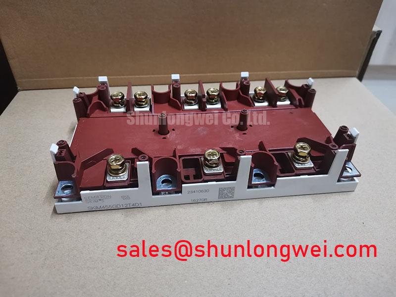
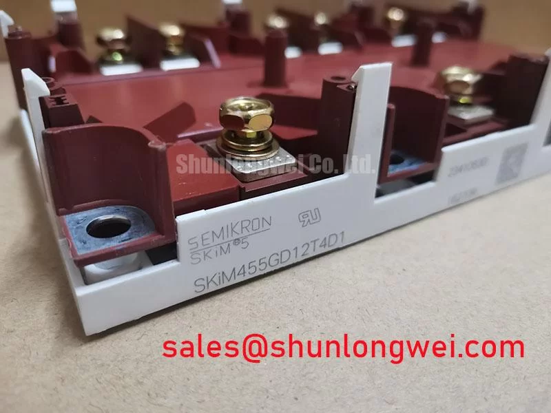
SKIM455GD12T4D1 Identification and Initial Checks
- Isolate the converter, verify that the DC link is discharged, and compare the module marking with the equipment service record before disconnecting power terminals.
- Check cold terminal impedance with the gate held in its specified off state, recording comparable measurements across equivalent converter branches.
- Inspect the heatsink contact surface, mounting hardware, and terminal alignment for uneven seating or mechanical loading.
- Trace the isolated gate supply and gate return against the converter schematic before enabling switching commands.
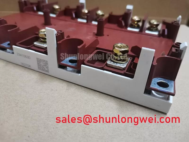
The SKIM455GD12T4D1 from Semikron is an IGBT module with specified ratings of 1200 V and 450 A. Repair and procurement decisions should connect these electrical ratings to the actual terminal arrangement, cooling interface, and driver configuration rather than treating the part number as a complete compatibility check.
| Product parameter | Specification | Engineering interpretation |
|---|---|---|
| Model | SKIM455GD12T4D1 | Match the complete ordering designation. |
| Manufacturer | Semikron | Manufacturer identity. |
| Rated voltage | 1200 V | Official Specification; distinguish the device blocking rating from the operating DC-link voltage. |
| Rated current | 450 A | Official Specification; apply the datasheet rating conditions when evaluating load capability. |
| Product family | SKiM | Consult the model datasheet drawing for dimensions and mounting details. |
| Integration-specific parameters | Consult Datasheet | Terminal map, internal circuit, gate limits, thermal data, insulation test conditions, and assembly requirements. |
Transient Dynamics & Electrical Design: Insulation Barrier Integrity on SKIM455GD12T4D1
Trace the isolation boundary between the controller, gate driver, auxiliary supply, and power terminals before investigating unwanted switching pulses. Design Consideration: module insulation and gate-driver signal isolation serve different functions; neither establishes reinforced insulation compliance for the complete converter. Working voltage, clearance, creepage, insulation coordination, and the applicable equipment standard belong to the assembled system assessment.
During controlled switching tests, compare the gate voltage measured locally at the module with the driver command and isolated supply waveform. Use appropriately rated differential instrumentation and keep the measurement loop compact. An apparent gate spike can include probe pickup, gate-return movement, or a real Miller-induced excursion. Separate these effects before changing the driver because an oscilloscope trace alone does not establish unintended device conduction.
Engineering Recommendation: reduce shared impedance between the gate return and high-current commutation paths, and evaluate the driver's immunity to common-mode voltage transitions under representative switching conditions. Negative off-state bias or active Miller clamping requires compatibility with the module's gate limits and the selected driver. The bias, clamp behavior, and protection timing are system-determined settings, not properties established by the module's voltage rating.
Manufacturer family information, including Semikron MiniSKiiP® Power Modules and Semikron-Danfoss SEMITRANS® Industry Standard IGBTs, provides context for different packaging approaches. These family pages should not be used to transfer pin assignments, isolation ratings, or mounting practices from one product family to SKIM455GD12T4D1.
Field Diagnostics & Commissioning: Preventing Mechanical Damage in SKIM455GD12T4D1 Assemblies
Check heatsink flatness and the module's seating condition before tightening mounting hardware. Design Consideration: uneven contact, contamination, or terminal-induced mechanical stress can compromise heat transfer and load the assembly unevenly. Assess contact geometry against the applicable mounting instructions rather than assuming a particular baseplate material, curvature, or internal substrate construction.
Apply the approved thermal interface material using the prescribed assembly process, then tighten fasteners progressively in the manufacturer's specified sequence. A calibrated tool helps control assembly variation, but neither torque nor interface thickness should be borrowed from another package. Inspect terminal alignment before connecting busbars so that tightening an electrical joint does not pull the module away from its cooling surface.
Commissioning also requires complementary gate-command verification. Engineering Recommendation: inspect turn-off completion, propagation-delay differences, and command interlocks before increasing load. Dead time should accommodate the measured switching behavior across the intended operating conditions without creating excessive diode conduction. A software interlock alone does not establish that both power devices remain mutually exclusive during driver supply disturbances or protection transitions.
Map the module's actual circuit position before evaluating related power components. The FZ1600R12KL4C can be considered separately when reviewing an adjacent power stage, but its suitability as a complementary component depends on the converter schematic; it should not be assumed to be a front-end rectifier or a compatible companion solely from its model designation.
Pro Tip: Consider symmetrical, compact commutation paths to reduce turn-off overshoot, then verify the resulting voltage margin with a suitably instrumented double-pulse test before accepting the layout.
Field Diagnostics & Commissioning: Thermal Network Simulation in SKIM455GD12T4D1 Topologies
Build the thermal assessment from the actual current waveform, switching pattern, and measured cooling boundary condition. Engineering Calculation: estimate conduction and switching losses using the model's applicable characteristic curves, then apply its transient thermal impedance to the resulting loss profile. Peak junction temperature depends on the preceding thermal history, not just the highest instantaneous current.
A multi-RC representation is useful when its coefficients reproduce the manufacturer's thermal response over the relevant pulse durations. Keep the network convention explicit: a fitted Foster network and a physical Cauer network are not interchangeable when attaching additional thermal stages. Use the temperature reference defined for the manufacturer's thermal model, and account separately for any interface or heatsink stages not included in that model.
Design Consideration: a temperature sensor near the assembly does not directly measure semiconductor junction temperature. Compare predicted temperatures with repeatable case or heatsink measurements taken at documented locations, and examine whether changes in contact pressure or cooling performance explain discrepancies. Abnormal heating may involve switching loss, electrical joint resistance, thermal contact, or unequal branch loading; the measurement sequence should distinguish these possibilities.
If SKIM455GD12T4D1 is being evaluated for a multi-megawatt offshore or onshore wind-turbine full-scale converter, assess the converter's actual branch architecture and duty profile rather than assigning a system power capability to one module. Regenerative energy handling and any associated braking chopper require their own loss assessment. A braking resistor's energy capacity cannot establish semiconductor pulse capability, and DC-link control behavior can change the stress seen by the switching stage.
For repeated charging, discharging, or braking cycles, compare temperature excursions and cooling recovery within the intended mission profile. Engineering Recommendation: reducing avoidable thermal swings can be a useful design objective, but a service-life prediction requires a validated reliability model and supporting manufacturer data. Thermal simulation alone does not justify a guaranteed operating lifetime.
SKIM455GD12T4D1 Operational Boundaries: Evaluating Derating Guidelines and Mismatched Parameter Limits
Compare replacement candidates by internal circuit, terminal arrangement, gate requirements, switching characteristics, and thermal interface before comparing headline current ratings. The FZ400R12KS4 is a cross-model comparison reference, not a declared interchangeable replacement for SKIM455GD12T4D1. Mechanical fit and matching voltage classes do not establish electrical equivalence.
Design Consideration: where the relevant output characteristics demonstrate a positive temperature coefficient of collector-emitter saturation voltage, that behavior can assist static current sharing over the applicable operating region. It does not guarantee dynamic sharing. Evaluate parallel branches for gate-path impedance, commutation-loop symmetry, cooling differences, and device variation; confirm branch currents during switching as well as steady conduction.
Assess freewheeling behavior using the applicable diode data and measured commutation waveforms. Reverse-recovery behavior affects current overshoot and electromagnetic emissions, but a softness factor should not be assigned without defined test conditions and supporting data. Similarly, reflected voltage in an attached motor cable belongs to the converter, cable, and load assessment; it is not a fixed additional voltage rating of this module.
The technical discussion in Unlocking Efficiency in Industrial Drives provides supplementary context for switching-loss and operating-margin evaluation. Its discussion of another IGBT technology is not a test standard and does not establish this model's semiconductor generation or operating limits.
Before release to service, record peak collector-emitter voltage, gate excursions, branch-current balance, protection response, and cooling conditions against the approved equipment limits. Retain the exact module designation and driver configuration with those measurements so that procurement and maintenance teams can distinguish a verified installation from a part-number-only substitution.