

Content last revised on September 22, 2026
Transient Dynamics & Electrical Design: DC Link Capacitance Bank Layout and Low ESL on P11B11
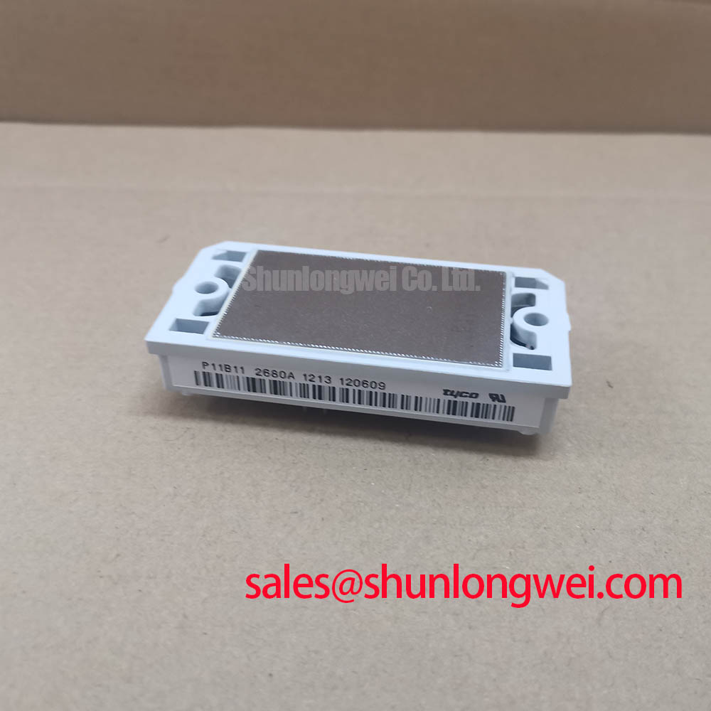
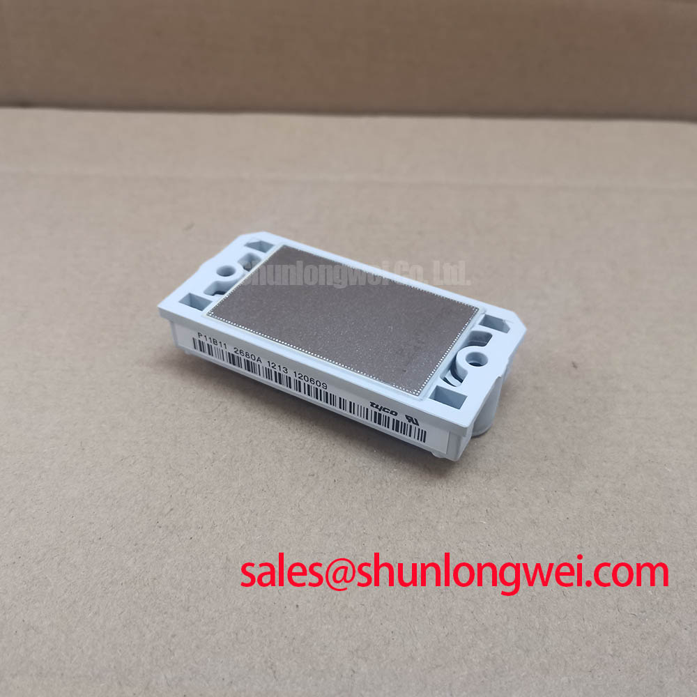
Before connecting a replacement module, verify the nameplate rating against the drive documentation, inspect the power terminals and baseplate contact area, and confirm that the application does not exceed the 1200 V rating or the 300 A rated-current value under its applicable conditions for the P11B11 power module from Tyco Electronics.
| Parameter | Specification |
|---|---|
| Model | P11B11 |
| Manufacturer | Tyco Electronics |
| Rated Voltage | 1200 V Official Specification |
| Rated Current | 300 A Official Specification; applicable conditions apply |
| Package | Power Module Official Specification |
The P11B11 is a 1200 V, 300 A power module for equipment where the DC link, switching path, and load current path must be assessed as one electrical assembly. In a heavy duty variable frequency AC motor drive, voltage overshoot is influenced by DC bus voltage, commutation current, switching transition speed, and parasitic inductance in the capacitor to module loop. Engineering calculation recognizes that peak switching voltage rises with loop inductance and the rate of change of current, so the physical DC link layout deserves the same attention as the module rating.
Design Consideration: place the local DC link capacitor bank so that its connection to the module power terminals follows the shortest practical current path. Broad, paired conductors or a symmetrical laminated bus structure can reduce loop area and help suppress turn off overshoot. Clearance, creepage distance, capacitor ripple capability, and enclosure conditions remain system determined and should be verified against the complete drive specification.
During commissioning, capture collector-emitter voltage and phase current with correctly rated probes while reproducing the actual motor load condition. A visible ringing pattern can point to interaction among busbar inductance, capacitor placement, gate transition speed, and measurement technique. It should not be assigned to one cause without comparing the result against a known good phase or a validated reference design.
For repair evaluation, DWM100X2 12U can be reviewed as a separate power module option when its terminal arrangement, voltage class, current duty, gate drive requirements, thermal interface, and protection settings are independently verified. Electrical interchangeability should never be inferred from current rating alone.
P11B11 Thermal Electrical Optimization: Differential Gate Source Loop Routing for Practical Tuning
Gate drive routing should be evaluated separately from the high current emitter return path. Shared power return inductance can couple switching current into the gate reference and alter the effective gate voltage during rapid transitions. Design Consideration: route each gate command and its return as a compact differential loop, keep it physically separated from the main power path where practical, and verify switching behavior at the module terminals.
The available P11B11 package documentation should be checked before assigning any auxiliary or sensing terminal function. A system integrator should not assume the presence of a dedicated Kelvin emitter connection from the module category alone. Where a suitable auxiliary reference terminal is confirmed, it can support a quieter gate measurement and drive return arrangement than a return shared with the main load current path.
In a half-bridge system, complementary drive commands require an interlock arrangement that prevents both switches in a leg from being commanded on at the same time. Dead time, driver propagation delay, device switching behavior, current direction, and controller timing are system determined. Bench adjustment should be validated with switching waveforms and fault protection active, rather than copied from a different inverter platform.
In systems using an upstream rectifier stage, engineers may also assess related components such as MBM200JS12EW as part of the overall DC supply topology. Its suitability depends on the rectifier duty, thermal conditions, protection arrangement, and original equipment documentation.
Assembly Integrity & Layout Architecture: Applying Transient Thermal Impedance to P11B11
The P11B11 power module should be mounted only after the heatsink surface is inspected for flatness, contamination, and localized damage. Thermal performance during repetitive overload is not represented by a single steady state condition. Junction temperature response depends on pulse duration, power dissipation, baseplate to heatsink contact quality, coolant or airflow conditions, and the transient thermal behavior stated in the applicable manufacturer documentation.
Engineering Recommendation: use the module specific thermal data, where available, together with the actual load cycle to calculate junction temperature margin. Multi section thermal models can describe how heat travels from junction to case over time, but the result remains dependent on the real heatsink assembly and measured operating losses. The integrator should confirm the calculated result through temperature measurement and representative load testing.
⚡ Safety Interlock Note: Isolate stored DC link energy and verify a safe residual voltage before touching module terminals, gate wiring, or bus connections.
Mechanical assembly should maintain even pressure across the module mounting surface and avoid stressing terminal connections through misaligned busbars. Mounting torque, thermal interface material selection, and terminal hardware requirements must be taken from the applicable module and equipment documentation rather than assumed from other power module families.
For broader context on waveform capture, thermal checks, and structured fault isolation, consult the Field Engineer’s Handbook. Industry resources from Semikron Danfoss Power Electronics also provide useful reference material on power semiconductor module integration practices.
Field Diagnostics & Commissioning: Negative Gate Bias and Active Miller Clamp in P11B11 Topologies
At high switching voltage slew rates, displacement current through device capacitances can raise the voltage on an off state gate. If the gate loop has excessive impedance or a noisy reference, unwanted turn on can contribute to cross conduction. Design Consideration: evaluate whether the existing driver uses negative gate bias, an active Miller clamp, or another validated method to hold the off state gate at a controlled potential during the opposite switch transition.
A negative gate bias level is not a universal setting. It must remain within the applicable module gate rating and be assessed alongside driver supply tolerance, gate resistance, reverse recovery behavior, isolation performance, and measured switching waveforms. An active Miller clamp can provide a low impedance discharge path when the gate is intended to remain off, but its timing and connection integrity require verification in the installed topology.
When diagnosing a drive that trips during acceleration or regenerative operation, inspect gate command timing, driver supply stability, DC link ripple, current sensing signals, and each phase leg waveform. Oscillation or asymmetrical switching may indicate an interaction between layout and gate drive conditions, requiring scope based comparison rather than a single component level assumption. The Semikron MiniSKiiP power module reference offers additional industry context for evaluating module based inverter assemblies.