Content last revised on September 10, 2026
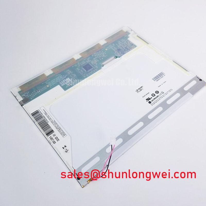
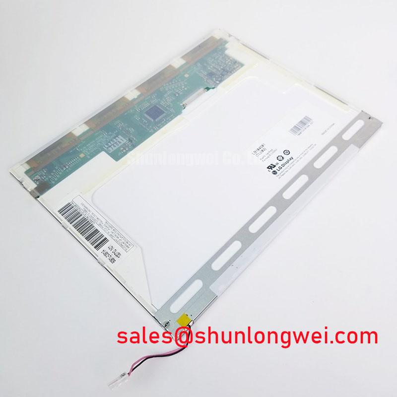
LB104S01-TL01 LG Display Industrial Grade LCD HMI Panel
Begin a replacement assessment by comparing the installed panel label, connector position, mounting outline, and controller interface with the LB104S01-TL01 documentation before applying power. The available factory context identifies this unit as an LG Display TFT LCD Display Module for industrial HMI use, with an Official Factory Spec Verified status for the listed product classification. Electrical and optical values not provided in the available specification context should be confirmed from the original panel documentation rather than inferred from a similar display.
| Model | LB104S01-TL01 |
| Manufacturer | LG Display |
| Product category | Industrial Grade LCD/HMI Panel |
| Construction classification | TFT-LCD Display Module |
| Specification status | Official Factory Spec Verified |
For equipment repair teams, the key decision is physical and electrical compatibility rather than a general screen-size comparison. Confirm the active area, bezel opening, overall envelope, connector orientation, cable reach, controller output format, backlight power method, and mounting arrangement against the failed assembly. A panel can appear mechanically similar while using a different timing format, pin assignment, or backlight interface.
Suppressing Localized Thermal Gradients to Prevent Chronic Optical Yellowing and Color Shift
Inspect the enclosure around the display for heat concentration before installing a replacement. Narrow metal rails, nearby power converters, heater elements, and restricted airflow can create localized temperature differences across the panel edge. This is a Design Consideration, not a confirmed internal construction detail of the LB104S01-TL01. The available factory data does not verify a PMMA light guide, a particular optical adhesive, an LED lifetime curve, or a specified L70 or B50 rating for this model.
When the panel is evaluated for a harsh marine radar or navigation bridge console, the system integrator should review heat transfer paths from adjacent electronics and the effect of enclosure sealing. An aluminum spreader may be considered where the chassis design creates a local hot spot, but its dimensions, contact pressure, and thermal interface must be determined from measured enclosure temperatures and the panel maker’s mechanical documentation. Do not clamp a spreader directly against the display glass or bezel without confirming the permitted contact areas.
Cold-start behavior also requires measurement. At low ambient temperature, liquid-crystal response can become slower, producing visible image trailing or timing changes during startup. The exact operating and storage temperature limits for this model are not included in the supplied factory parameter set, so engineers should obtain those limits from the original panel documentation. If a cabinet heater is present, its control method should be validated against the panel’s permitted warm-up conditions rather than selected from a generic LCD rule.
Color shift and apparent yellowing should be assessed with the same image pattern, luminance setting, ambient temperature, and viewing angle used for the known-good assembly. A photographic comparison alone is insufficient for a procurement decision. Check the optical path, cover glass, anti-glare layer, and enclosure reflections as separate contributors. The Industrial Display & HMI Solutions reference can support broader integration and environmental review, while model-specific limits still require confirmation from the panel documentation.
Backlight Inverter and Ignition Debugging
Do not assume that the LB104S01-TL01 uses a CCFL backlight or an LED backlight from the model designation alone. The supplied official context identifies the product as a TFT-LCD Display Module but does not state the backlight technology, lamp count, ignition voltage, current requirement, dimming method, or brightness specification. The system integrator should verify the required backlight supply and control signals from the original panel documentation and the installed display controller.
For a suspected CCFL installation, inspect the inverter output wiring, lamp connectors, insulation condition, grounding path, and enable signal with power removed before conducting energized tests. High-voltage ignition testing requires equipment rated for the circuit and a procedure appropriate to the inverter. A failed start can involve the inverter, lamp circuit, connector insulation, control timing, or supply instability; it should not be assigned to the panel without comparing the complete signal and power path with a known-good assembly.
For an LED configuration, verify the driver’s constant-current requirements, enable polarity, dimming input, fault reporting, and connector pinout. A PWM dimming ratio or half-life value cannot be attributed to this model without a source. The same restriction applies to claims about acoustic buzz, sunlight contrast, or a specified contrast ratio at a particular illuminance. In a bridge-console evaluation, use controlled luminance and viewing tests to determine whether the display remains readable behind the installed cover and under direct ambient light.
The external reference on Power MOSFET Structure and Operating Principles may help explain switching devices used in an inverter or backlight driver, but it does not establish the electrical specification of this LG Display panel. For a repair involving a controller connected to an industrial network, the Ethernet Powerlink reference is relevant to deterministic network architecture, not to the LCD’s native electrical interface.
Chassis Fastener Loading and Optical Mura Evaluation
Before fitting the module into a replacement bezel, compare the original opening, support ledges, rear clearance, connector access, and screw locations. The available factory parameters do not provide an outer bezel envelope, hole pattern, allowable panel distortion, or approved fastener torque for LB104S01-TL01. Therefore, a specific M3 torque range must not be presented as an official value for this model.
A suitable Design Consideration is to distribute mechanical loading evenly and avoid tightening one corner fully before the opposite corners are seated. The final fastening method should follow the panel drawing or the equipment manufacturer’s assembly procedure. If no documented torque is available, the mechanical team should establish a controlled process using the actual bezel, gasket, fastener, and support structure, then verify the image at uniform gray, black, and white test patterns.
Dark-field mura, edge brightening, pressure marks, and non-uniform luminance can originate from several interacting conditions, including bezel contact, uneven support, cover-window stress, connector loading, or backlight uniformity. A visible defect therefore requires comparison before and after mounting, not a single-cause diagnosis. Photograph the unmounted and installed states under identical camera exposure, and record whether the pattern changes when the panel is gently released from the chassis. Do not press the display surface as a diagnostic shortcut.
For low-temperature equipment, repeat the mechanical and optical inspection after the enclosure reaches its intended operating condition. Thermal expansion differences between the chassis and display assembly may alter contact pressure. If an alternative panel is being assessed, the TCG084SVLQAPNN-AN30-S page can be reviewed as a separate same-class sourcing reference; it should not be treated as a drop-in replacement until active area, resolution, interface, backlight, and mechanical drawings have been matched.
Display Interface Synchronization and Logic Power Rail Verification
Never connect the display cable solely by matching connector shape. The available factory context does not confirm whether LB104S01-TL01 uses TTL RGB, LVDS, a particular JEIDA or VESA mapping, a 24-bit data path, or a defined logic supply voltage. The original panel data sheet and controller documentation must establish the pin assignment, signal polarity, pixel-clock relationship, power sequence, reset behavior, and backlight controls.
During a bench check, begin with power disconnected and map every cable position against the documented pinout. Inspect for reversed orientation, damaged contacts, shield termination issues, and a controller configured for a different pixel format. Once the wiring is verified, use an oscilloscope and current-limited supply to observe the logic rail, enable signals, reset timing, and video timing at the panel connector. A split image, incorrect color order, unstable frame, or absent picture may indicate a mapping, timing, supply, or signal-integrity mismatch; compare each waveform with the known-good signal path instead of assigning the fault to the LCD immediately.
For TTL routing, designers should keep return paths continuous, separate noisy backlight or inverter wiring from pixel-clock and data conductors, and verify timing at the receiving connector. If the actual interface is LVDS, the system design must instead follow the documented differential pair assignment, polarity, termination, and cable construction. Characteristic impedance, pair matching, and any JEIDA or VESA selection are system-level requirements and must not be assigned to this model without documented confirmation.
The same verification applies to the logic supply. Do not select between possible voltage options based on a generic TFT-LCD convention. The system integrator should verify the required supply voltage from the original panel documentation, then check startup and shutdown behavior against the controller specification. Backlight brightness, dimming response, and fault recovery should be tested independently from video synchronization. If the wider assembly uses a separate display or backlight support module, NL10276BC30-18 may be examined as a related sourcing reference, subject to complete electrical and mechanical compatibility review.
💡 Pro Tip: Keep high-speed display signal returns continuous and verify the pixel-clock waveform at the panel connector, because connector-level noise can be hidden by a clean controller-side measurement.