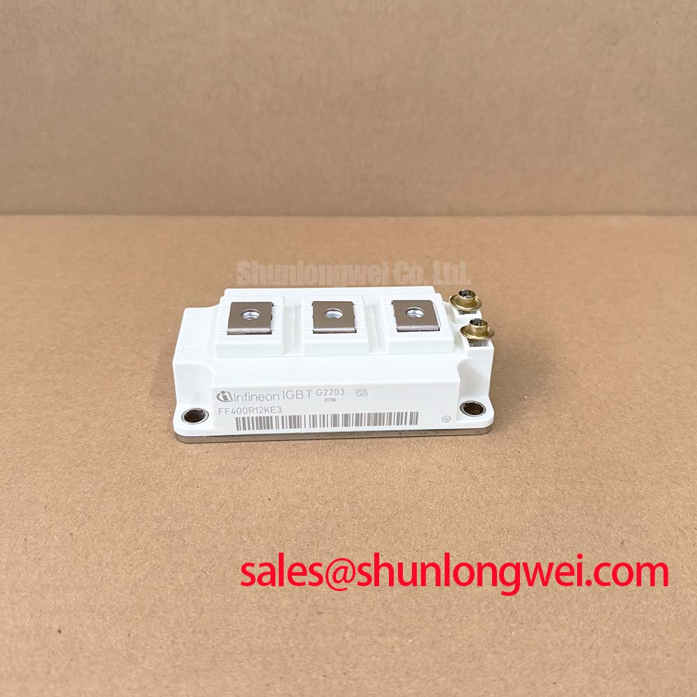
Content last revised on September 20, 2026
FS300R17KE4 Circuit Protection & Reliability: Transmission-Line Impedance Mismatch
Before energizing a replacement assembly, verify the inverter nameplate limits, inspect the FS300R17KE4 housing and terminals for handling damage, and compare the original circuit connection points against the service drawing. This Infineon IGBT module is officially rated at VCES = 1700 V and has an official nominal collector-current rating of 300 A at TC = 80°C. Its specified maximum operating junction temperature is 150°C.
Long motor cables and distributed winding capacitance can create reflected switching-wave behavior. Where the cable impedance differs materially from the inverter output impedance, the voltage at the motor-side terminal can rise above the initial inverter terminal transition. Under unfavorable reflection conditions, a terminal event can approach twice the inverter-side voltage step. This is a Design Consideration, not an FS300R17KE4 factory switching guarantee: the observed result depends on cable construction, route length, motor winding characteristics, grounding arrangement, operating state, and the actual gate-drive transition.
For a maintenance investigation, capture the inverter output and DC-link behavior with appropriately rated differential measurement equipment while comparing the affected phase with a known-good phase. Inspect the motor cable shield termination, output filter wiring, contactor condition, and phase-to-phase cable consistency before attributing the event to the power module. Repeated nuisance protection events during cable changes, motor replacement, or alternate operating modes can indicate a system-level impedance issue that needs waveform verification.
When the measured voltage transition creates inadequate system margin, designers should evaluate an output reactor or dv/dt filter appropriate to the motor, cable, and inverter topology. Such parts influence both the voltage seen at the motor terminals and the current-transition behavior at the module. Their suitability must be confirmed through switching tests rather than selected from a generic cable-length rule.
MOV-based transient suppression can also be considered at the system level where the applicable protection architecture supports it. The MOV selection must account for its coordination with the DC-link, protective fusing, expected surge-energy environment, and degradation behavior. An MOV should not be treated as a substitute for controlling the commutation loop or validating the actual turn-off transient.
For service teams evaluating a higher-current reference within the same voltage class, the FF45017ME4 can be reviewed as a separate component option. Electrical ratings, mechanical interface, gate-drive conditions, cooling performance, commutation behavior, and protection settings must all be checked against the original equipment documentation before any compatibility decision.
⚠️ Maintenance Note: Monitor terminal and heatsink contact temperature during scheduled operation, and keep the cooling-air path free of dust accumulation that can obscure a developing thermal problem.
FS300R17KE4 Operational Boundaries: Evaluating Dynamic Power Loss Dissipation and Multi-R Limits
The FS300R17KE4 uses the EconoPACK™+ IHM-B module housing. The official junction-to-case thermal resistance is 0.066 K/W per IGBT. This value is an official device parameter, but it does not by itself establish the junction temperature in a complete inverter. Heatsink resistance, thermal interface condition, clamping quality, airflow or liquid-cooling behavior, switching loss, conduction loss, and load profile all contribute to the operating result.
For pulsed overload analysis, use the manufacturer thermal-impedance information applicable to the part and calculate the time-dependent junction response from the actual power-loss waveform. A multi-R thermal representation is useful because a short high-energy pulse and a sustained load interval do not produce the same thermal response, even when their average power appears similar. The system calculation should combine conduction and switching losses over the relevant operating interval, then compare the resulting peak junction estimate with the official 150°C maximum operating junction-temperature limit.
This is an Engineering Calculation when it is based on measured or documented current, voltage, switching frequency, gate-drive conditions, cooling data, and the applicable thermal model. It should not be replaced with a calculation based only on the 300 A nameplate current. The structured parameter listing also identifies 300 A and 400 A nominal collector-current entries; engineers should confirm the exact datasheet condition and circuit configuration relevant to the installed module before assigning an operating limit.
Commutation-loop inductance remains important during turn-off because the parasitic inductance converts rapid current change into additional voltage overshoot. A layered busbar arrangement, close-coupled DC-link capacitor connection, and short symmetric conductor paths are Design Considerations used to reduce that effect. The final allowable layout must be established from the measured peak collector-emitter voltage under the intended current, temperature, and gate-drive conditions.
Film capacitors placed close to the active commutation path can reduce the effective high-frequency loop area, provided their voltage rating, ripple capability, connection geometry, and fault behavior are suited to the converter. A snubber network can alter the transient waveform, but it also changes loss distribution and thermal loading. Designers should validate these tradeoffs on the finished assembly rather than assuming that a capacitor addition resolves every overshoot event.
Periodic cooling-system review is part of the same boundary check. Inspect heatsink fin blockage, fan operation, coolant flow where applicable, thermal-interface aging, and mounting-contact condition. A clean module can still run hotter than expected when the heat path between case and heatsink has deteriorated. The gate-drive timing and protection thresholds should also be reviewed after a power-stage repair; the Precision Gate Drive Design reference provides useful context for evaluating the relationship between switching behavior, protection response, and device stress.
Preventing Spurious Faults: Differential Gate-Emitter Loop Routing Guidelines for FS300R17KE4
When a repaired inverter presents intermittent gate-protection trips, ringing, or unequal behavior between otherwise similar phases, begin by tracing each gate-drive loop as a pair. The gate signal and its driver return must be assessed together. Shared impedance with the main power-emitter current path can couple a voltage disturbance into the gate-reference path during switching, making the effective gate-emitter voltage differ from the command expected by the controller.
This is especially relevant in high-current converter assemblies because the power loop carries a rapidly changing current while the gate drive is attempting to make a comparatively small-signal decision. The preferred Design Consideration is to keep the driver reference path separate from the main high-current return path where the module interface and original equipment design provide that arrangement. Do not infer an unverified internal terminal structure from a generic IGBT layout. The system integrator should follow the original FS300R17KE4 connection documentation and confirm each terminal assignment before reconnecting the driver board.
During troubleshooting, inspect gate connectors, driver-board solder joints, shielded or paired control wiring, connector retention, and the physical route of the return conductor. Compare waveforms at the module-side connection rather than only at the controller output, because a clean command waveform at the controller does not prove that the module receives the same effective gate condition. A differential probe measurement can help distinguish a gate-loop disturbance from a current-sensor, control-supply, desaturation, or logic-interlock event.
Gate resistor selection, turn-on and turn-off command levels, fault blanking intervals, and desaturation settings are system-determined values. They should be retained from the qualified equipment design unless a controlled validation program is being performed. A changed resistor or substituted driver can alter switching loss, overshoot, electromagnetic behavior, and protection timing. No universal gate setting can be assigned from the module voltage and current rating alone.
For technical background on reverse-conducting IGBT behavior and diode-related switching considerations, consult the Infineon RCDC application note. It provides context for assessing reverse-current paths without treating a general application note as a part-specific declaration for this module.
For operational maintenance, recheck terminal tightness according to the original equipment manufacturer’s documented torque and sequence. Loose power or control connections can introduce heat, noise, and unstable measurements. In low-temperature industrial environments, inspect for condensation risk at shutdown and restart, especially around driver boards, connectors, and cooling interfaces. The required enclosure and moisture-control measures are system-level responsibilities.
FS300R17KE4 Operational Boundaries: Evaluating Braking-Resistor Sizing and Chopper Transistor Limits
During motor deceleration, the driven load can return energy to the DC link. If the upstream source or regenerative path cannot accept that energy, DC-link voltage rises until the control system diverts energy through a braking chopper and ballast resistor, reduces deceleration demand, or uses another approved energy-management path. The 1700 V collector-emitter rating of the FS300R17KE4 is an official blocking-voltage specification; it does not define the permissible DC-link setpoint, braking threshold, resistor value, or chopper duty cycle for a particular inverter.
Braking-resistor evaluation should start with the actual deceleration energy, repetition pattern, available cooling, resistor pulse capability, enclosure temperature, and the DC-link protection sequence. The chopper transistor must be assessed for its own voltage, current, switching, and thermal limits. If the FS300R17KE4 is used in a relevant power-stage position, its loading must likewise be calculated from the actual topology and waveform rather than assumed from its nominal current label.
A service diagnosis should record DC-link behavior during the commanded deceleration event and compare it with the equipment’s documented protective thresholds. Inspect the braking resistor for connection integrity, thermal damage, clearance from heat-sensitive wiring, and ventilation restrictions. Verify the chopper drive signal and protective control logic with suitable isolated measurement methods. A rising DC link may relate to braking-circuit behavior, but it can also involve load conditions, line-side operation, controller commands, sensing accuracy, or an inhibited regeneration path.
For potential equipment compatibility review, engineers sometimes assess a module of this class for a high-speed rail or heavy-freight locomotive traction inverter. That assessment must remain specific to the original topology, cooling system, control strategy, insulation coordination, and railway equipment requirements. The module itself should not be presented as independently certified for a complete traction, EMC, or safety system.
The physical behavior of modern IGBT modules is also discussed in the external technical article on Infineon TRENCHSTOP™ IGBT7. Use such material as industry context only; confirm all replacement decisions against the official FS300R17KE4 documentation and the original inverter design.