Content last revised on September 23, 2026
Field Diagnostics & Commissioning: DC-Link Capacitance Bank Layout and Low-ESL in BSM100GT120DN2 Topologies
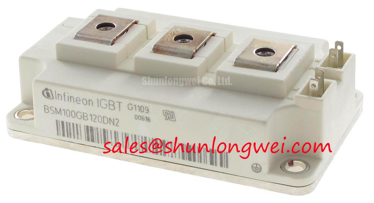
With the DC link fully discharged, begin incoming inspection by checking the terminal markings against the original power-stage drawing and comparing each cold diode-mode reading with a known-good assembly where available. The BSM100GT120DN2 is an Infineon IGBT module with a specified 1200 V collector-emitter voltage rating and 100 A collector-current rating. Before commissioning, inspect the module case, power terminals, mounting surface, and gate connections for contamination, distortion, loose hardware, or signs that the installation stack has been disturbed.
| Official Specification | Value |
|---|---|
| Manufacturer | Infineon |
| Part Number | BSM100GT120DN2 |
| Collector-Emitter Voltage Rating | 1200 V |
| Collector-Current Rating | 100 A (verify the applicable datasheet conditions) |
| Package | Module |
💡 Bench Tip: Use ESD controlled handling and record cold-state measurements before energizing the converter, because comparative readings are more useful than a single isolated meter result.
For a power stage using the BSM100GT120DN2, inspect the physical route from the DC-link capacitor bank to the module terminals before blaming the module for switching overshoot. At turn-off, the observed peak voltage is influenced by DC-bus voltage plus the product of stray inductance and current-change rate. This is an Engineering Calculation relationship, not an official voltage-clamp rating for this part. A wide, closely coupled bus structure and short return path are Design Considerations intended to reduce loop inductance and limit ringing.
During commissioning, measure the DC-link waveform with probing appropriate for the voltage and transient environment. A repetitive ringing pattern can be associated with bus geometry, capacitor placement, probe technique, snubber condition, or gate-drive behavior. Check capacitor terminals, laminated or planar conductor contact, and symmetry between parallel current paths. Where a snubber network is present, its capacitor, resistor, wiring, and thermal condition should be evaluated as one assembly rather than treated as an isolated component.
Industrial inverter welders and medium-frequency induction heating power supplies are potential evaluation contexts for this module, subject to verification of the original circuit topology, switching conditions, cooling arrangement, and control-board interface. For a same-class reference during documented compatibility review, see FS100R12N2T4. The comparison should remain limited to verified electrical, mechanical, and drive-interface data.
BSM100GT120DN2 Operational Boundaries: Evaluating Active Miller Clamp Implementation Limits
Check gate and emitter connections at the driver connector before applying PWM signals. A gate trace that appears to rise while its device is intended to remain off may indicate capacitive coupling, excessive shared inductance, unsuitable driver return routing, or measurement interference. It does not establish one single fault cause. Verify the waveform against the known-good channel and inspect the gate-driver supply rails, logic isolation path, and drive enable sequence.
An active Miller clamp is a Design Consideration in gate-drive systems where high switching-node voltage slew rate could couple charge into a disabled gate. Whether a clamp, an off-state bias arrangement, or a gate resistor network is appropriate is determined by the full driver circuit and must be verified through switching tests. Designers should confirm that phase-angle control behavior, line-frequency ripple, and transient suppression measures do not create unintended gate pulses under the actual load profile.
When reviewing related devices within the same power assembly, BSM75GD120DLC can be examined as a separate system-topology reference. Its presence in a related circuit does not establish electrical interchangeability with the BSM100GT120DN2.
Transient Dynamics & Electrical Design: Reinforced Insulation Barrier Integrity on BSM100GT120DN2
The BSM100GT120DN2 module rating does not by itself define the reinforced isolation performance of the completed converter. Inspect the drive board, isolated power supplies, optocouplers or digital isolators, harnesses, terminal barriers, and enclosure clearances as distinct parts of the insulation system. The system integrator should verify isolation requirements from the original equipment documentation and applicable safety standard.
Common-mode transients can disturb control signals when the driver isolation barrier, return routing, or measurement arrangement is inadequate for the installation. Use an oscilloscope setup suited to the live voltage environment and compare gate commands, driver supply references, and switching-node behavior during controlled testing. Keep high-current power conductors separated from low-level control wiring where the assembly permits, and inspect creepage and clearance distances for contamination or conductive debris.
For broader practical context on IGBT operating principles and test interpretation, consult The Ultimate IGBT Knowledge Base. Infineon also provides an official IGBT portfolio and technical background on 1200 V high-speed IGBT behavior.
Preventing Spurious Faults: Regenerative DC-Bus Voltage Surge Dissipation Guidelines for BSM100GT120DN2
When an inductive load returns energy to the DC link, first determine whether the original equipment uses a braking path, regenerative front end, clamp network, or another energy-management method. A DC-bus rise during load deceleration can originate from operating sequence, insufficient energy absorption, sensing error, or a disconnected braking path. Capture bus voltage, command state, and load transition data together before replacing parts.
A braking IGBT and ballast resistor, where used by the original design, must be assessed as a coordinated subsystem. The resistor mounting, thermal path, wiring, control threshold, and protection logic are system-determined. Designers should verify that regenerated energy is controlled within the voltage boundaries of the entire converter, including the 1200 V rating of the BSM100GT120DN2.
⚡ Safety Interlock Note: Disconnect and verify discharge of the DC-link capacitors before touching module terminals, snubber parts, or braking-circuit wiring.