



Content last revised on September 27, 2026
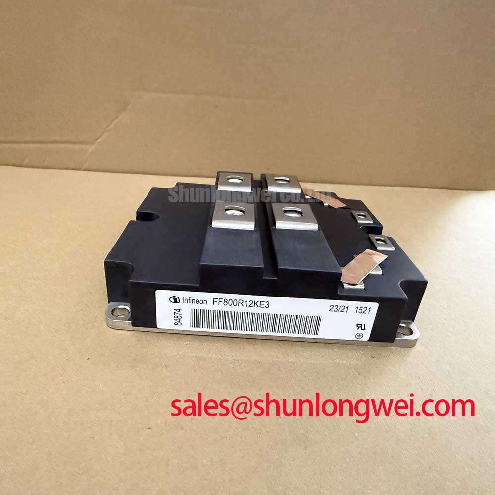
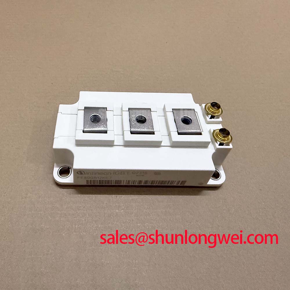
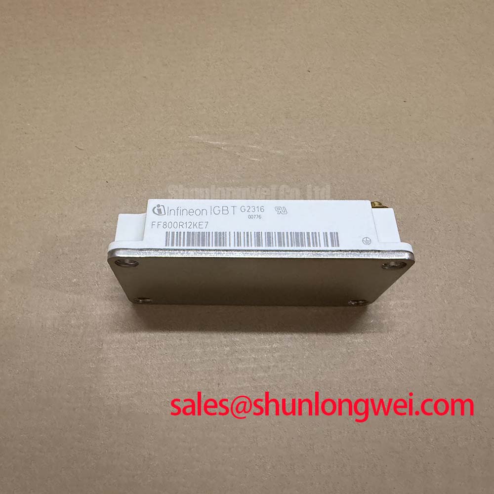
FF800R12KE7 Infineon 1200V 800A IGBT Module
With the inverter isolated and discharged, first inspect the FF800R12KE7 housing, verify the nameplate rating, and compare cold terminal resistance with a known good assembly before reconnecting the DC link or gate driver.
The FF800R12KE7 is an Infineon high power IGBT module using TRENCHSTOP™ IGBT7 technology. Its published electrical ratings make it a candidate for evaluation in high power inverters, motor drives, commercial vehicle power systems, and selected utility scale solar inverter platforms. Compatibility with a specific 1500V central photovoltaic inverter must be confirmed from the original converter schematic, DC link architecture, switching waveform, cooling system, and gate driver documentation. The module voltage rating must not be treated as an automatic approval for a 1500V DC bus.
| Official parameter | Published value | Engineering interpretation |
|---|---|---|
| Collector emitter voltage, VCES | 1200 V | Voltage blocking capability for high voltage converter stages, subject to system transient verification |
| Nominal collector current, IC nom | 800 A at TC = 90°C | High current capability under the stated case temperature condition |
| Collector emitter saturation voltage, VCE(sat) | Typical 1.70 V at IC = 800 A and Tvj = 25°C | Conduction loss reference under the specified test conditions |
| Maximum operating junction temperature, Tvj op | 150°C | Upper operating junction temperature stated for normal operation |
| Overload junction temperature | 175°C | Short duration overload reference, not a continuous operating target |
| Technology | TRENCHSTOP™ IGBT7 | Infineon power semiconductor technology platform |
FF800R12KE7 Thermal Electrical Optimization and High Altitude SEB Review
For a replacement assessment, begin at the equipment boundary rather than assuming that the previous module failed alone. Record the measured DC link voltage, switching frequency, phase current, cooling inlet condition, and the highest observed case temperature. The official 1200 V VCES rating defines the blocking capability of the device, while the actual converter must also control switching overshoot, commutation inductance, regeneration events, and abnormal operating conditions.
Single event burnout, cosmic ray sensitivity, and altitude related failure rates require a device specific reliability source and a defined application test method. No universal FIT value or altitude derating percentage should be assigned to this module without the relevant Infineon qualification information and the converter operating profile. At elevations above 2000 m, designers should treat reduced cooling capability, insulation coordination, air pressure, and transient voltage stress as separate verification items. The system engineer should evaluate peak collector emitter voltage during switching tests against the DC link voltage and the applicable insulation design requirements.
Layout review should focus on minimizing the commutation loop area and keeping high current paths symmetrical. Busbar spacing, creepage, clearance, and enclosure contamination control are system design considerations, not automatic properties of the IGBT module. A 1500V photovoltaic inverter may use several conversion stages, so the integrator should verify whether this 1200V device is located on an isolated lower voltage stage or whether a different voltage class is required for the direct DC link.
During a field inspection, compare the suspect module with the circuit position that shares the same electrical function. Check for cracked molding, discoloration near the terminals, loose busbar joints, and signs of uneven thermal transfer. A resistance test can identify gross abnormalities, but it cannot validate dynamic switching performance. If the static checks are inconclusive, use controlled low energy testing and an oscilloscope to compare gate emitter and collector emitter waveforms with the known good phase.
For a neutral technology reference when reviewing alternative semiconductor topologies, consult The 1200 V CoolSiC™ MOSFET Advantage in Three-Phase Power Conversion. It provides useful system context, but it does not establish interchangeability with this IGBT module.
FF800R12KE7 Circuit Protection and Dynamic Gate Impedance Control
Gate drive verification should begin with the original schematic and terminal identification supplied for the exact assembly. Do not infer pin functions from a visually similar module. Confirm the gate, emitter, collector, auxiliary emitter, and any parallel connection points against the approved mechanical drawing before applying a driver signal. The required gate voltage, gate resistance, turn on and turn off strategy, and protection thresholds are system determined.
High common mode transients can couple into the gate loop and create unwanted turn on in an opposing device. A low inductance gate loop, controlled return path, suitable gate driver isolation, and an active Miller clamp may be considered where the switching test shows excessive gate disturbance. Negative gate bias is not an automatic requirement for this model. If a negative bias is evaluated, the driver designer must verify the module datasheet limits, driver output capability, insulation coordination, and turn off transient behavior.
Dead time should be established from measured turn off delay, current commutation behavior, driver propagation tolerance, temperature variation, and the actual load. A fixed value copied from another module can increase either cross conduction risk or diode conduction loss. Verify both devices in the half bridge with a differential probe and confirm that the gate signal remains within the approved limits during the fastest switching transition.
Protection hardware should coordinate short circuit response, gate driver fault reporting, DC link discharge, and controlled shutdown. The Infineon High Power Semiconductor Solutions resource is a suitable manufacturer reference for broader power semiconductor architecture. The Infineon CIPOS™ Maxi IPM Series is a separate product family and should not be treated as a direct mechanical or electrical substitute.
Field Alert: Disconnect the DC link and gate driver supply before removing cables, and follow the original mechanical drawing for terminal identification and fastening procedure.
Preventing Spurious Faults with Desaturation Detection
Desaturation protection should be reviewed as part of the complete gate driver circuit rather than as an isolated module feature. The protection designer should verify the sensing method, blanking behavior, fault filter, gate shutdown profile, and response to normal diode recovery. The correct response time depends on the short circuit safe operating area, driver propagation delay, stray inductance, and the energy that can be released by the connected DC link.
A two stage soft turn off may be considered when an abrupt gate discharge would create excessive inductive voltage overshoot. The first action reduces the stored gate charge in a controlled manner, while the subsequent shutdown isolates the fault according to the driver architecture. This is an engineering recommendation for bench evaluation, not an official FF800R12KE7 timing specification. The final protection sequence must be validated with current probes and high voltage differential measurements under the worst credible fault condition.
False desaturation trips can be associated with sensing layout, common emitter inductance, diode recovery, insufficient filtering, or a gate driver reference that moves during commutation. These possibilities should be separated through waveform measurement rather than assigned to a single cause. Check the fault line at the driver, compare it with the collector emitter waveform, and inspect whether the event occurs only at high temperature, high current, or a particular modulation state.
Fast fuses and semiconductor protection devices also require coordinated I2t evaluation. The fuse clearing characteristic, module short circuit withstand capability, busbar inductance, and DC link energy must be assessed together. A fuse rating copied from another inverter cannot establish protection for this module. The system engineer should verify the complete fault path and confirm that the overall protection sequence limits module short circuit and thermal stress to permitted levels.
FF800R12KE7 Derating and Mismatched Parameter Tuning
The published 800 A nominal collector current at TC = 90°C is a defined rating condition, not a universal current guarantee at every heatsink temperature, switching frequency, pulse width, or cooling airflow. Thermal design should include conduction loss based on the stated typical 1.70 V VCE(sat) test point, switching loss from the actual gate resistance and load waveform, and the transient thermal impedance of the mounted assembly. The resulting junction temperature must remain within the applicable operating limits, with the 150°C maximum operating junction temperature treated as a boundary rather than a target.
Parallel operation requires more than matching part numbers. Static current sharing can benefit from the positive temperature behavior of IGBT conduction voltage, but dynamic sharing remains sensitive to gate loop inductance, driver delay, emitter path impedance, busbar symmetry, and thermal coupling. Each parallel path should use a mechanically symmetrical current route and a closely matched gate return arrangement. The measured collector current of each device should be checked during turn on, steady conduction, and turn off.
If a replacement is being considered across product families, engineers may review FZ800R12KS4_B2 as a separate reference for comparison. It is not a stated drop in replacement for FF800R12KE7. Mechanical outline, terminal arrangement, gate charge, switching behavior, thermal interface, isolation characteristics, and protection settings must all be checked before any substitution decision.
For a utility scale central photovoltaic inverter, the final compatibility review should confirm the converter stage voltage, phase leg topology, cooling plate condition, gate driver supply, fuse coordination, and measured switching overshoot. Procurement teams should also provide the original equipment part reference and revision when requesting a replacement assessment, because the same cabinet may contain modules with different electrical roles.