


Content last revised on March 29, 2026
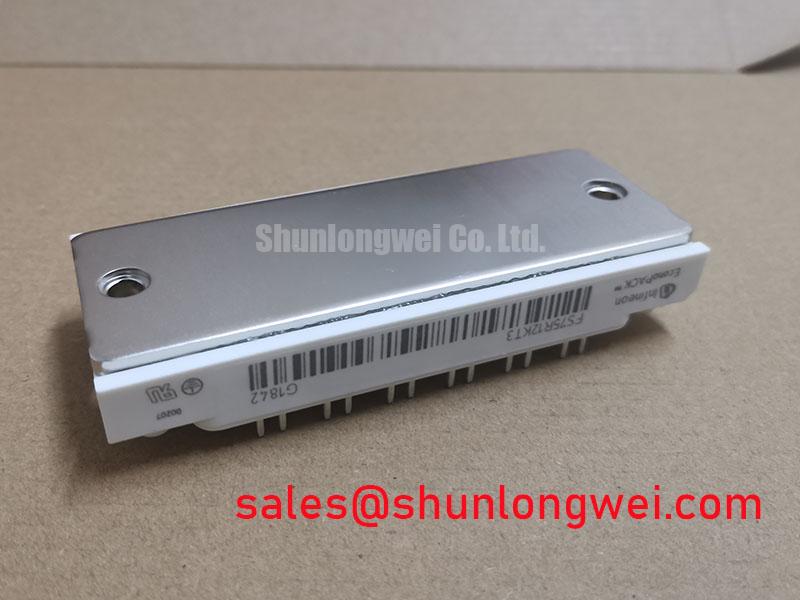
FS75R12KT3 IGBT Module: Technical Data for Inverter Design
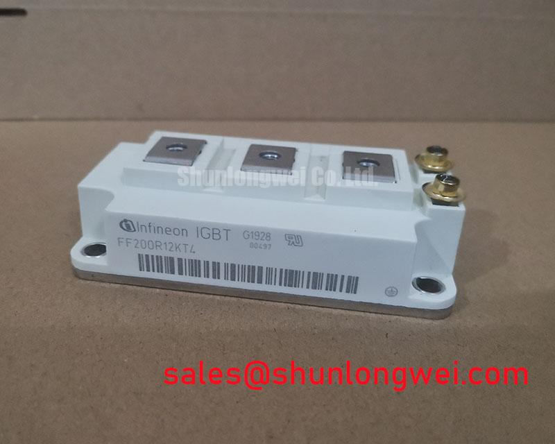
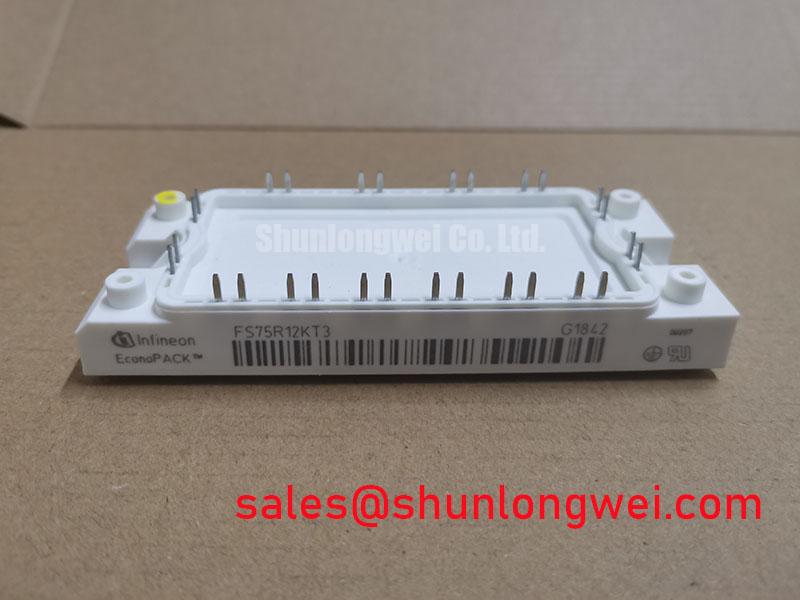
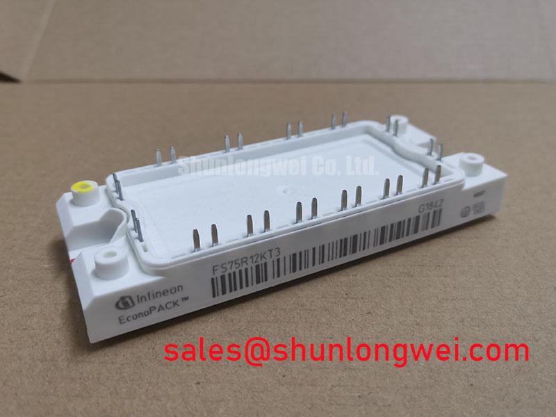
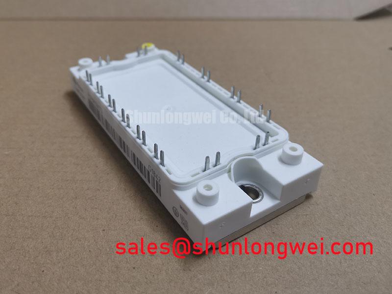
Optimized for high-frequency switching, the Infineon FS75R12KT3 leverages TRENCHSTOP™ IGBT3 technology for superior inverter efficiency and thermal performance.
This 6-pack module delivers a robust solution for power conversion systems where minimizing total energy loss is a primary design objective. Key specifications include: 1200V Collector-Emitter Voltage | 75A DC Collector Current | 150A Repetitive Peak Current. The design offers tangible engineering benefits such as reduced heatsink requirements and increased power density. By integrating proven TrenchSTOP™ IGBT3 silicon, this module directly addresses the challenge of balancing conduction and switching losses, a critical factor for achieving high performance in modern variable frequency drives and solar inverters.
Strategic Efficiency Gains in Modern Power Conversion
The push for higher energy efficiency ratings in industrial equipment, such as IE4 and IE5 class motors, places significant demands on the power electronics stage. The FS75R12KT3 directly supports this trend by employing TRENCHSTOP™ IGBT3 technology. This silicon design is engineered to reduce VCE(sat), which lowers conduction losses, while simultaneously managing switching losses (Eon and Eoff). For system architects, this translates into inverters that not only consume less power during operation but also generate less waste heat. This thermal dividend allows for more compact mechanical designs, potentially smaller and less costly heatsinks, and improved overall system reliability by maintaining lower operating temperatures.
Datasheet-Driven Comparison for System Design
When evaluating power modules, a direct comparison of key parameters provides the clearest path for an informed engineering decision. The data below is presented to facilitate a factual assessment based on datasheet values. This information is intended to support your design analysis and component selection process.
Consider the following comparison between two related 1200V, 75A modules:
- FS75R12KT3 (TRENCHSTOP™ IGBT3): This module features a typical collector-emitter saturation voltage (VCE(sat)) of 1.70V (at Tj=25°C, IC=75A). Its typical total switching energy (Ets) at Tj=125°C and IC=75A is 7.4 mJ.
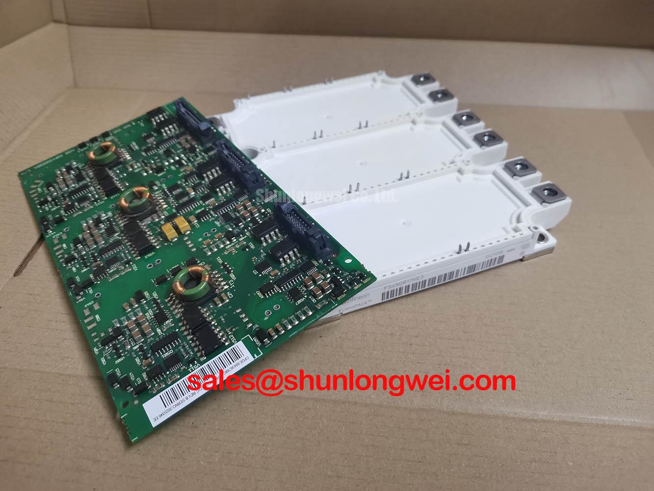
- FS75R12KE3 (Fieldstop IGBT2): As an alternative technology, this module presents a typical VCE(sat) of 2.15V under the same conditions. Its typical total switching energy is specified differently, reflecting variations in technology generations and test conditions, which necessitates careful review of the respective datasheets for a direct application-specific comparison.
This data highlights how different IGBT generations offer distinct trade-offs between conduction and switching performance, enabling engineers to select the component that best aligns with their application's specific frequency and load profile.
Core Electrical and Thermal Specifications at a Glance
The following parameters for the FS75R12KT3 are derived directly from the official manufacturer's datasheet. This table format is designed to provide not just the value, but the engineering context for each specification, aiding in system-level design and simulation. For a comprehensive list of all parameters, characteristics, and graphs, please refer to the official documentation.
| Parameter | Value | Engineering Insight |
|---|---|---|
| Collector-Emitter Voltage (Vces) | 1200 V | Provides the necessary voltage margin for applications connected to 400/480VAC lines, ensuring reliability against voltage transients. |
| DC Collector Current (Ic nom / ICRM) | 75 A / 150 A | Defines the nominal and peak current handling capability, suitable for motor drives in the 15 kW to 30 kW power range. |
| Collector-Emitter Saturation Voltage (VCE(sat), typ. @ Tj=125°C) | 2.0 V | A low VCE(sat) directly reduces conduction losses, which dominate at lower switching frequencies. This value is critical for calculating overall system efficiency. |
| Total Switching Energy (Ets, typ. @ Tj=125°C) | 7.4 mJ | Represents the energy lost during turn-on and turn-off events. A lower value is crucial for high-frequency applications (e.g., >8 kHz) to minimize thermal load. |
| Thermal Resistance, Junction to Case (RthJC per IGBT) | 0.36 K/W | This parameter is the thermal equivalent of electrical resistance; it dictates how effectively heat can be transferred from the IGBT chip to the module's baseplate. A lower number signifies more efficient heat removal. |
| Short Circuit Withstand Time (tsc) | 10 µs | Specifies the duration the module can safely withstand a direct short circuit before failure, a critical safety parameter for fault protection circuit design. |
Download the complete FS75R12KT3 Datasheet for detailed charts and application notes.
Application Focus: Where Low-Loss Switching Excels
The specific performance characteristics of the FS75R12KT3 make it a well-suited component for several power conversion applications where efficiency and thermal management are paramount.
Industrial Motor Drives
In modern Variable Frequency Drives (VFDs), higher switching frequencies enable smoother motor operation, reduced audible noise, and smaller filter components. The low switching losses of the FS75R12KT3 are a direct asset here, containing the heat generated at frequencies from 8 kHz to 16 kHz. What is the benefit of its integrated NTC thermistor? It provides crucial, real-time temperature feedback for precise thermal management and overload protection. For motor drives up to 30kW requiring high switching frequencies, the FS75R12KT3's low Eon/Eoff of 3.4/4.0 mJ makes it a thermally superior choice.
Solar Power Inverters
Maximizing energy harvest is the core objective of a solar inverter. The module's high efficiency, stemming from the balance between low VCE(sat) and minimal switching losses, contributes directly to a higher Maximum Power Point Tracking (MPPT) efficiency, converting more DC power from the panels into usable AC power for the grid.
Uninterruptible Power Supplies (UPS)
In double-conversion UPS systems, the inverter stage is continuously active. The efficiency of the FS75R12KT3 reduces the system's baseline power consumption, leading to lower operating costs over the equipment's lifespan and reducing the cooling burden within data centers or industrial facilities.
A Technical Analysis of TRENCHSTOP™ IGBT3 Performance
The performance of the FS75R12KT3 is rooted in its TRENCHSTOP™ IGBT3 chip technology. Unlike earlier planar IGBT designs, the trench-gate structure creates a vertical current path that significantly increases the carrier concentration in the drift region. This fundamental design change is the primary reason for its lower on-state voltage drop, or VCE(sat). What is the primary benefit of TRENCHSTOP™ technology? It achieves a superior trade-off between low on-state voltage and minimal switching losses.
Understanding power loss in an IGBT can be compared to a highway system for electrons. Conduction loss (related to VCE(sat)) is like a low, continuous toll paid while current is flowing—the lower the toll, the less energy is wasted. Switching loss (Eon/Eoff) is akin to the energy spent braking and accelerating to get through the toll plaza; it happens only at turn-on and turn-off but becomes more significant the more frequently you pass through (i.e., at higher switching frequencies). The FS75R12KT3 is engineered to minimize both of these "tolls," leading to a more efficient journey for the power.
Deployment Scenario: A Glimpse into Inverter Integration
An engineering team developing a new 22kW servo drive was tasked with reducing the unit's overall volume by 15% compared to the previous generation. A primary challenge was the size of the heatsink, which was dictated by the thermal load from the power stage. By selecting the FS75R12KT3 and operating at a 10 kHz switching frequency, the team's thermal simulations confirmed a 20% reduction in total power losses compared to the older IGBT technology they were using. This reduction in waste heat allowed for the design of a smaller, more compact heatsink, directly enabling them to meet the product's size-reduction targets while improving the drive's overall energy efficiency.
Frequently Asked Questions
1. What is the primary advantage of the EconoPIM™ 2 housing for this module?
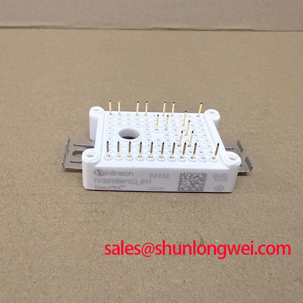
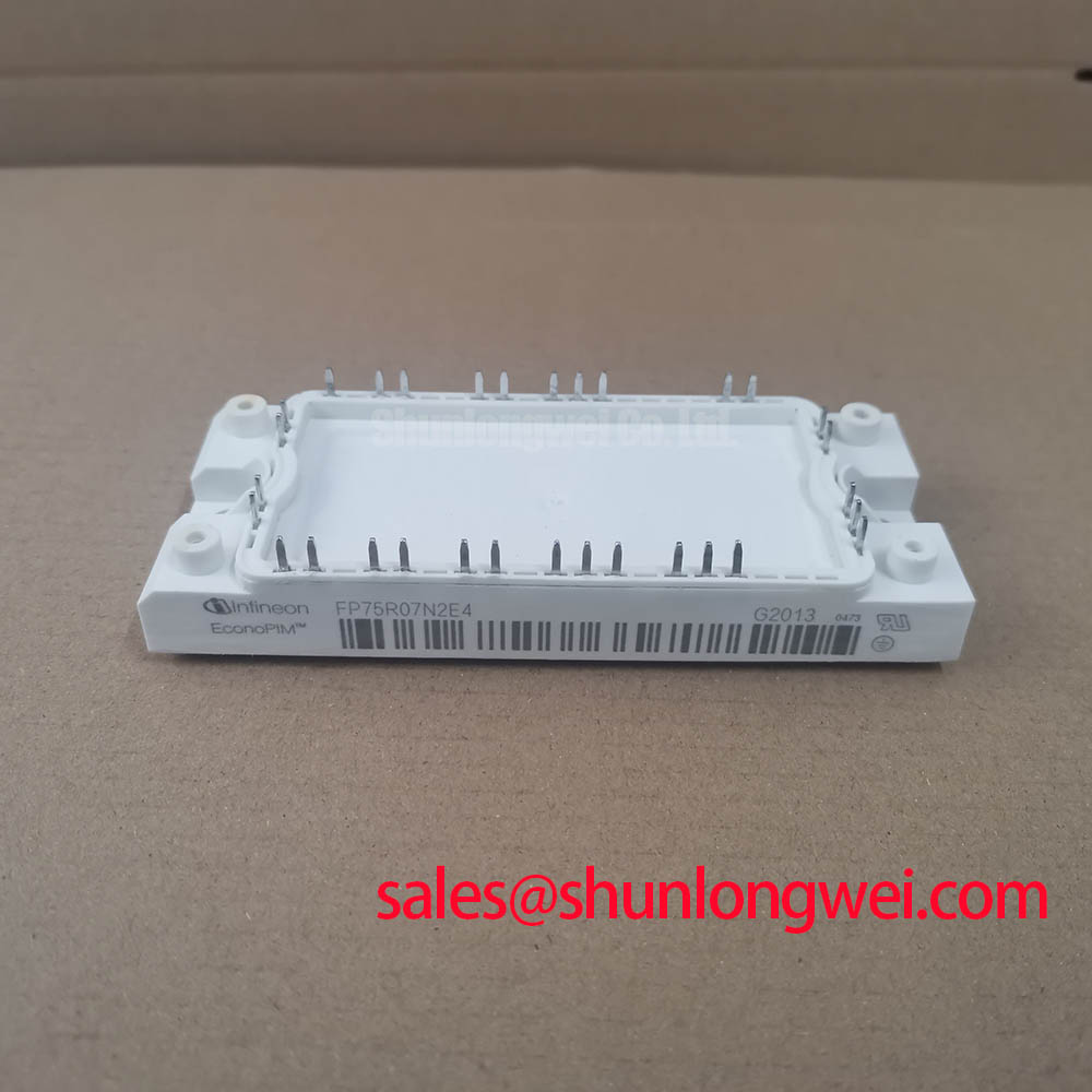
The EconoPIM™ 2 housing integrates a three-phase input rectifier, a brake chopper, and the three-phase inverter stage into a single, compact module. This high level of integration simplifies the power stage layout, reduces component count, and accelerates the assembly process for applications like all-in-one motor drives.
2. How does the integrated NTC thermistor in the FS75R12KT3 improve system reliability?
The built-in Negative Temperature Coefficient (NTC) thermistor provides a direct, real-time measurement of the module's internal temperature. This allows the drive's control system to accurately monitor thermal load, implement precise over-temperature protection, and potentially throttle output power gracefully before a critical shutdown is necessary, thus preventing catastrophic failure and enhancing long-term operational safety.
3. Can the FS75R12KT3 be used in parallel to achieve higher current output?
While paralleling IGBT modules is a common practice, it requires careful design considerations. The positive temperature coefficient of the VCE(sat) in the FS75R12KT3 is beneficial for thermal balancing between parallel modules. However, designers must ensure symmetrical busbar layouts and optimized gate driver circuits to prevent current imbalances and switching oscillations. For detailed guidance, consulting an application note on IGBT paralleling is strongly recommended.
4. Compared to newer IGBT generations like IGBT4 or IGBT7, what is the key trade-off with TRENCHSTOP™ IGBT3?
TRENCHSTOP™ IGBT3 technology represents a well-established balance between conduction and switching performance. Newer generations, like IGBT4, often optimize for even lower VCE(sat) at the expense of slightly higher switching losses, making them ideal for lower-frequency applications. Conversely, IGBT7 is typically optimized for lower switching losses and higher power density. The FS75R12KT3 remains a strong choice for applications in the 4-16 kHz range where this specific balance provides the optimal efficiency point.
5. What type of gate driver is recommended for the FS75R12KT3?
For optimal performance, a gate driver capable of providing a gate voltage of +15V for turn-on and a negative voltage between -8V and -15V for turn-off is recommended. The negative turn-off voltage ensures a high immunity against parasitic turn-on, especially during high dv/dt events. A driver with a peak current capability of several amperes is also necessary to charge and discharge the IGBT's gate capacitance quickly, minimizing switching losses.
An Engineer's Perspective on Future Optimization
From a design standpoint, the FS75R12KT3 provides a solid foundation for efficient and reliable inverter design. For future system iterations, engineers might explore leveraging the module's thermal headroom. By implementing more advanced cooling techniques, such as liquid cooling or phase-change materials, it may be possible to push the operational power density even further. Additionally, pairing this module with a sophisticated gate driver that allows for on-the-fly adjustment of the gate resistor (Rg) could enable dynamic optimization of the switching profile, balancing EMI performance against efficiency in real-time to meet varying load conditions.