
Content last revised on October 8, 2026
Fault-Clearing Dynamics: Type-I/II Desaturation Detection and Inductive Clamping
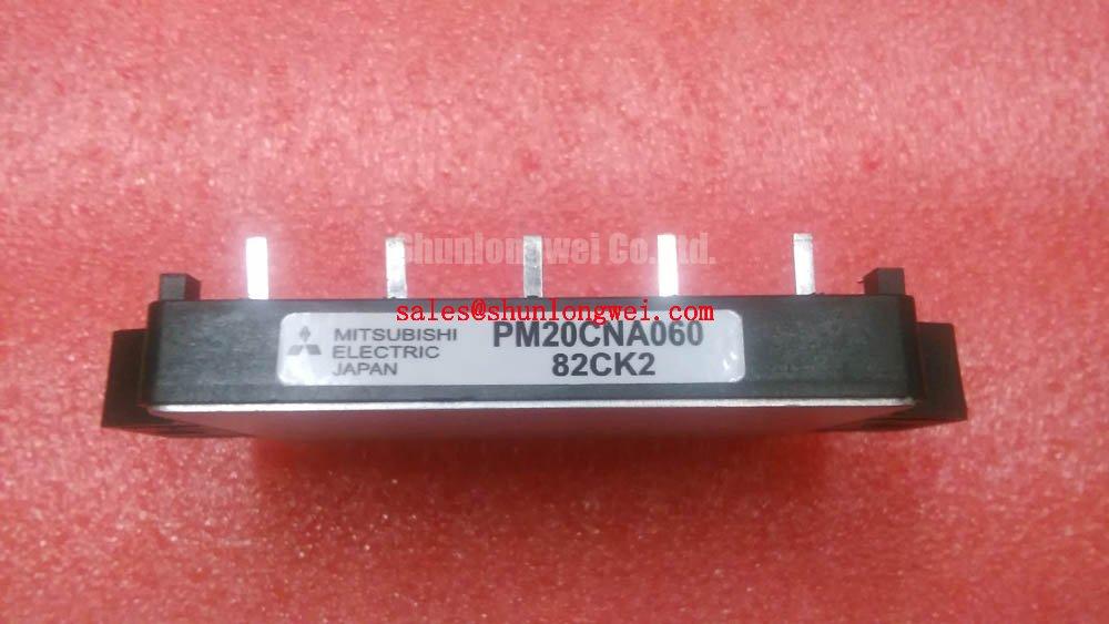
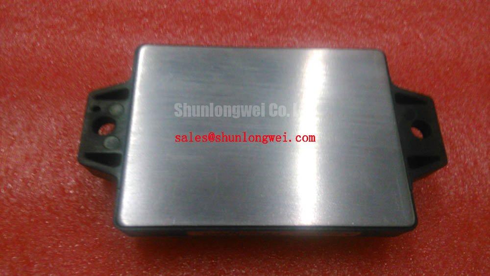
With the servo drive isolated and its DC link verified discharged, check the PM20CNA060 nameplate against the removed module before disconnecting its control harness. Mitsubishi Electric identifies this device as an IPM module rated at 600 V and 20 A (Official Specification). Those ratings establish a starting boundary for a precision stepper or BLDC servo actuator repair; they do not, by themselves, establish pin compatibility, protection timing, thermal capacity, or suitability for a particular motor.
Begin fault analysis at the drive schematic. Trace the DC link, inverter output, control supply, fault output, and any external current-sensing path, then compare the harness and terminals with the original equipment documentation. A drive that reports a short circuit may be responding to an output-stage fault, a motor-cable fault, or a control-interface problem. Record the fault indication before clearing it, and inspect the motor leads and load independently of the module.
Type-I and Type-II short-circuit events present different stresses: a switch may be commanded on into an existing fault, or a fault may develop while current is already flowing. Desaturation detection and soft turn-off are relevant protection concepts, but neither a detection time nor a two-stage turn-off sequence is established by the supplied PM20CNA060 ratings. Treat any timing target, including a microsecond-level target, as a system requirement to verify against the applicable Mitsubishi documentation and the drive’s protection circuit. Do not infer a short-circuit safe operating interval from the 20 A current rating.
During controlled troubleshooting, compare the fault signal, current indication, and switching waveform with a known-good drive where available. If a fault follows a commanded transition, inspect the gate-control return path and the layout around the power loop before attributing it to the motor. As a Design Consideration, keep the commutation loop compact to limit inductive turn-off overshoot, then measure peak voltage under representative operating conditions against the module’s 600 V rating. Creepage, clearance, and harness spacing must be checked against the actual assembly and its governing requirements rather than assigned a generic distance.
An external Miller clamp or altered gate network should not be assumed compatible with an intelligent power module. First establish what control and protection functions are internal, which terminals are accessible, and whether the original drive permits changes. The same caution applies to dead-time adjustments: inadequate interlock can permit shoot-through, while excessive dead time can affect motion quality. Protection changes require waveform validation in the complete drive.
Evaluating Thermal Capacitance vs Heat Sink Time Constant under Surge Bursts
A servo actuator can impose short, repeated current demands during acceleration, holding corrections, or regenerative deceleration. The heat sink may appear cool while the semiconductor junction is responding to a much faster pulse. For the PM20CNA060, the available official information confirms the 20 A rating but does not provide a transient thermal impedance curve, case-temperature limit, or surge-current allowance. Those missing values cannot be replaced with an assumed overload multiplier.
Where the applicable manufacturer thermal data is available, an Engineering Calculation can estimate a pulse-related junction rise by applying the loss pulse to its specified transient thermal impedance, then adding the relevant starting temperature. A multi-RC model is useful when the duty cycle contains bursts separated by incomplete cooling periods; its coefficients must come from applicable device data or validated thermal measurement. Check both the peak junction estimate and the temperature reached after repeated bursts. The heat sink’s slower response is not evidence that each junction pulse remains within limits.
For a repair assessment, document the operating sequence rather than testing only at steady speed. Capture acceleration demand, dwell time, switching conditions, and heat-sink temperature at a repeatable measurement point. Review the interface between the module and heat sink for uneven contact, contamination, and displaced thermal compound. Thermal-interface material thickness and mounting torque should follow the module and equipment instructions; neither value is confirmed by the supplied PM20CNA060 specifications.
⚠️ Field Alert: Do not reuse a mounting torque from a visually similar module without checking the PM20CNA060 installation documentation and the heat-sink hardware.
If the actuator regenerates energy during deceleration, examine the DC-link voltage trend and the drive’s braking path as well as semiconductor temperature. A braking chopper and resistor, when present in the equipment, must absorb energy according to their own ratings and control strategy. A rising DC link may reduce switching-voltage margin even when measured heat-sink temperature changes little. This is a system-level check, not a claimed braking feature of the module.
Thermal Feedback & VCE(sat) Positive Temperature Coefficient Equalization
Temperature changes semiconductor conduction behavior, but a positive temperature coefficient of VCE(sat) must not be assumed across every current and temperature condition. Nor does the PM20CNA060 rating establish that its internal switches are intended for parallel operation. If a drive uses parallel power paths, consult the applicable device curves and equipment schematic before drawing conclusions about static current sharing.
Dynamic imbalance calls for a separate check. Compare conductor length, connection resistance, and the physical route of each control and power return path in the installed assembly. Symmetry helps limit unequal switching behavior, but the presence of a Kelvin auxiliary-emitter terminal or an accessible Miller-clamp connection must be confirmed from the actual pin documentation. 💡 Pro Tip: Keep any documented gate-control return close to its corresponding control path, then verify switching behavior at the installed module rather than judging symmetry by harness appearance alone.
When a repaired drive heats unevenly, inspect the heat-sink contact pattern and measure operating conditions before assigning the cause to VCE(sat). Differences in load phase, switching command, cooling airflow, or contact pressure can produce similar observations. The Field Engineer’s Handbook provides a broader framework for organizing electrical and thermal fault checks.
Cross-model selection needs the same discipline. CM15MD-12H may appear during a procurement comparison, but a different part number is not a drop-in replacement on the strength of voltage and current figures alone. Compare the manufacturer’s terminal map, control interface, protection behavior, mechanical fit, and thermal conditions before the equipment owner approves any substitution.
Suppression of 2x VDC Voltage Doubling at Inverter-Driven Motor Terminals
At the far end of a long motor cable, a fast inverter edge can reflect where cable impedance meets the motor termination. Under particular cable and edge conditions, the first terminal-voltage step can approach twice the incident step. That is a transmission-line design consideration, not a measured voltage or guaranteed outcome for the PM20CNA060. The module’s 600 V rating concerns its specified device voltage boundary; it does not certify motor-winding insulation or establish a permissible cable length.
Measure at the motor terminals with instrumentation suited to the waveform, then compare the result with the motor and drive documentation. Record cable type, routing, length, grounding arrangement, and operating condition so a change in waveform can be interpreted. If an output filter or choke is being evaluated, its selection belongs to the drive design: account for motor current, switching behavior, added loss, and control response, and verify the installed result. Do not select a filter solely from the module’s 20 A rating.
In a precision motion system, separate electrical output faults from position-feedback faults. A rotary encoder’s quadrature channels provide direction and incremental position information; the rotary encoder reference explains that signal relationship. Compare commanded motion with feedback and measured phase behavior before replacing power hardware for a positioning alarm. Applicable equipment requirements should also be checked with the relevant standards framework, such as information published by NEMA; the module rating alone establishes no equipment-level compliance.
Finally, check the front end that supplies the inverter. DC-link ripple, rectifier behavior, and regenerative energy handling can change the stress seen during a motor-cable test. SKIIP 31 NAB 063 T1 is a separate device that may arise when reviewing associated power-stage hardware, not an assumed companion or interchangeable part. Use the equipment schematic to determine its actual role before comparing parts or interpreting measurements.