


Content last revised on March 29, 2026
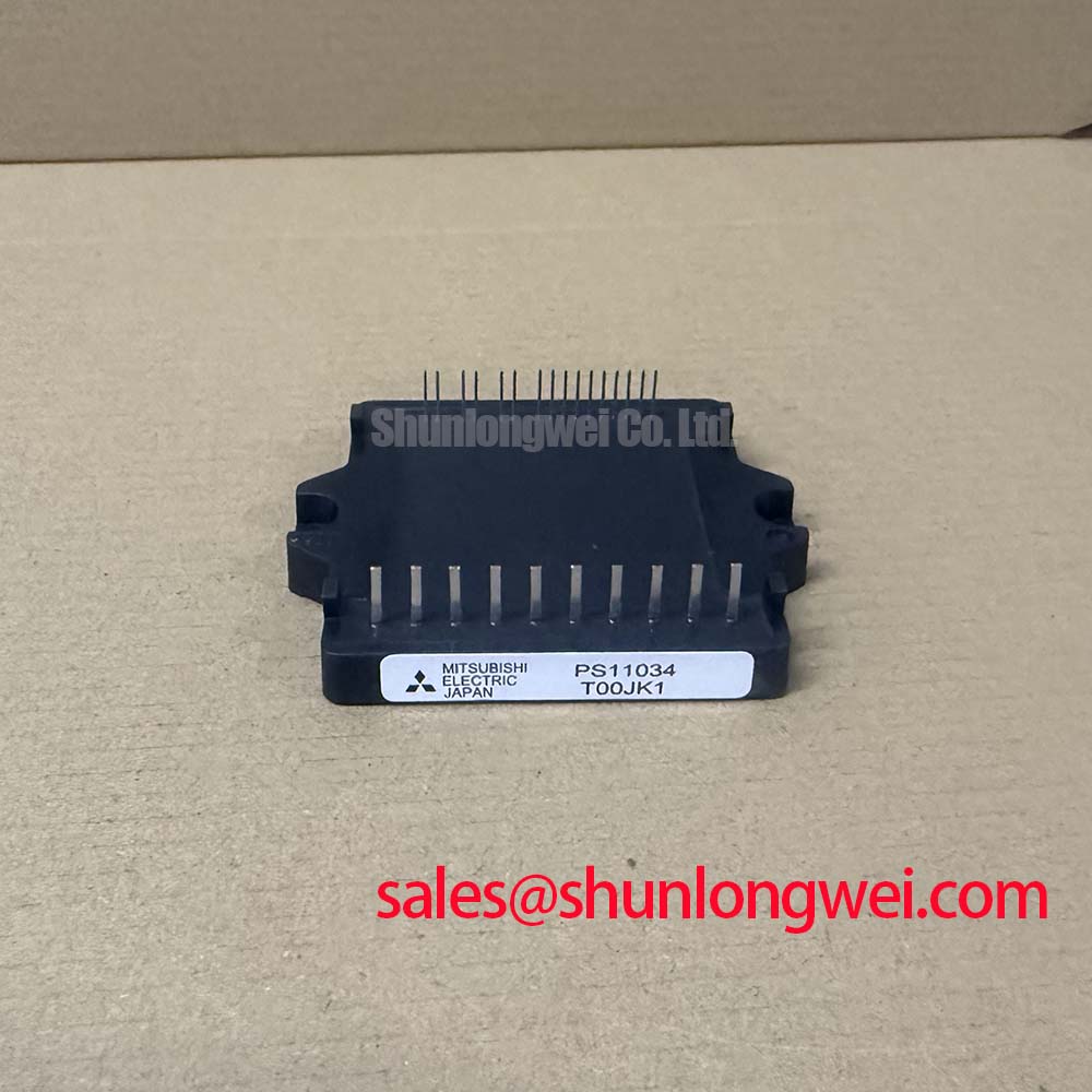
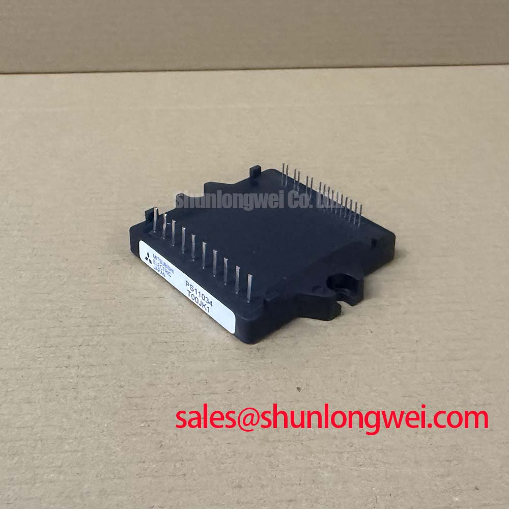
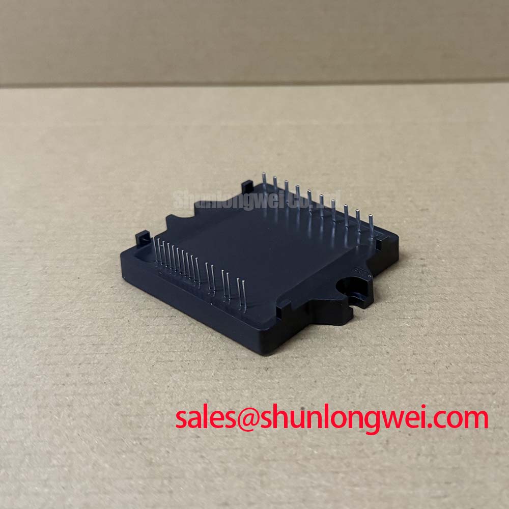
PS11034: Mitsubishi 15A/600V Integrated Power Module
Streamline 0.75kW Inverter Design with a Fully Integrated Power Stage
The Mitsubishi PS11034 radically simplifies the design cycle for compact motor drives by embedding a full three-phase converter and inverter into a single, optimized package. It is an Application Specific Intelligent Power Module (IPM) that delivers a complete power solution for systems up to 0.75kW. With key specifications of 600V | 5.0A (I_O) | 2.2V (V_CE(sat)), this module offers accelerated development and reduced PCB footprint. Its integrated bootstrap circuit enables a simplified single-source power supply scheme, directly answering the engineering need for lower system complexity and cost. By consolidating power devices, gate drivers, and a full suite of protection features, the PS11034 serves as an assembly-ready foundation for next-generation, compact motor control.
From Component Sprawl to a Single Module: The Strategic Edge
In the drive towards more distributed and compact industrial automation, engineers are constantly challenged to increase power density while shrinking development timelines. The traditional approach of designing a power stage with discrete rectifiers, IGBTs, gate drivers, and protection logic involves significant engineering effort in component selection, layout, and thermal management. The PS11034 Application Specific Intelligent Power Module directly addresses this challenge.
This module encapsulates the entire power conversion chain—from AC input rectification to the final three-phase PWM output. This level of integration provides a significant strategic advantage, shifting the design focus from low-level circuit implementation to high-level system control and application features. This philosophy aligns perfectly with modern agile development, where rapid prototyping and validation are key. For more insight into this design shift, explore our guide on IPM vs. Discrete IGBTs.
Core Specifications for Streamlined Integration
The technical parameters of the PS11034 are tailored to facilitate rapid integration into low-power motor drive systems. The datasheet provides comprehensive data for precise design calculations. Download the PS11034 datasheet for complete specifications.
Inverter Section (Tj = 25°C)
| Parameter | Symbol | Value | Unit |
|---|---|---|---|
| Collector-Emitter Voltage | V_CES | 600 | V |
| Collector Current (DC) | ±I_C | 5 | A |
| Collector Current (Pulse) | ±I_CP | 10 | A |
| Collector Power Dissipation | P_C | 14.7 | W |
| Collector-Emitter Saturation Voltage | V_CE(sat) | 2.2 (Typ.) / 2.7 (Max.) | V |
Converter Section (Tj = 25°C)
| Parameter | Symbol | Value | Unit |
|---|---|---|---|
| Repetitive Peak Reverse Voltage | V_RRM | 600 | V |
| DC Output Current | I_O | 5 | A |
| Surge Forward Current (60Hz, 1 cycle) | I_FSM | 60 | A |
Parameter Spotlight: The Integrated Protection System
A standout feature of the PS11034 is its integrated protection and fault output (Fo) pin. This single pin acts as a centralized warning system for the host microcontroller. Think of it like the "check engine" light in a car; instead of needing separate sensors to monitor over-current, short-circuit, and control voltage, the IPM flags a general fault, allowing the system to take immediate protective action. This simplifies software and hardware for fault handling, a key aspect of building dependable systems.
Data-Driven Evaluation: PS11034 in Context
When evaluating power modules, it's crucial to compare them based on the application's primary objective. The PS11034 is engineered for maximum integration in the sub-1kW space. While other discrete solutions might offer slightly lower VCE(sat) or faster switching, they cannot match the PS11034's value proposition in terms of space savings and design simplification.
For systems prioritizing minimal footprint and fastest time-to-market over cutting-edge efficiency, the PS11034 is an excellent fit. For higher power applications requiring more advanced thermal management, a larger module such as the PS11035 (10A) from the same family might be considered. The choice depends on a clear analysis of system-level trade-offs between size, cost, and performance, a topic further explored in our guide to decoding datasheets.
Where Integration Accelerates Development
The highly integrated nature of the PS11034 makes it a strong candidate for specific applications where space, reliability, and development speed are paramount.
- Appliance Motor Control: Ideal for driving motors in washing machines, fans, and pumps where a compact and reliable "all-in-one" solution reduces assembly complexity and cost.
- Small Industrial Pumps and Fans: Well-suited for auxiliary motors and ventilation systems in industrial settings that require a dependable, low-maintenance drive.
- Automated Gate and Door Openers: The integrated protection and simple interface are beneficial for commercial and residential access systems.
- Laboratory and Office Automation: Its low acoustic noise profile makes it suitable for equipment operating in quiet environments.
What is the main benefit of its integrated converter? It eliminates the need for an external diode bridge, saving significant PCB space. For 200V AC line-powered drives targeting the 0.75kW power class, this module provides an unparalleled level of integration over discrete designs.
From Theory to Practice: Deployment Scenarios
Consider the design of a compact variable speed drive for a conveyor belt system. Using discrete components, the engineering team would need to design and lay out a rectifier stage, six IGBTs with their corresponding gate drivers, bootstrap circuits, current sensing, and over-current/under-voltage detection logic. This translates to dozens of components and significant PCB real estate.
By implementing the PS11034, the entire power section is reduced to a single component. The layout is simplified to connecting the AC input, DC link capacitor, motor outputs, and the low-voltage control signals from the microcontroller. This not only shrinks the final product but also drastically reduces the risk of layout-induced EMI and gate drive issues, as these critical high-frequency paths are optimized within the module by the manufacturer, Mitsubishi Electric.
Engineering Questions on the PS11034
What is the function of the "Fo" (Fault Output) pin on the PS11034?
The Fo pin is an open-collector output that serves as a centralized fault indicator. It transitions to a low state when the module's internal protection logic detects an N-side short-circuit (SC), over-current (OC), or a control supply under-voltage (UV). This allows the host microcontroller to immediately disable PWM signals and enter a safe state, enhancing system reliability.
How does the PS11034 simplify the gate drive power supply design?
The module incorporates a bootstrap circuit for the high-side (P-side) IGBT gate drivers. This design uses the switching action of the low-side IGBTs to charge capacitors that provide the floating supply for the high-side drivers. This intelligent feature, common in Intelligent Power Modules (IPM), allows the entire module to be operated from a single low-voltage control supply, eliminating the need for multiple isolated power sources and significantly simplifying the overall system power architecture.
Anatomy of an Integrated Power Stage
The Mitsubishi PS11034 is more than just a collection of components; it is a system-in-a-package. Internally, it is architected for synergy between its constituent parts. The core consists of a three-phase diode bridge for AC-to-DC conversion and a three-phase inverter bridge built with third-generation IGBT technology. This is augmented by a sophisticated control IC that performs several crucial functions:
- High-Side Gate Driving: Integrated high-voltage level-shifters and bootstrap circuits provide the correct floating gate voltage to the P-side IGBTs without requiring separate isolated supplies.
- Low-Side Gate Driving: N-side IGBTs are driven directly, with integrated protection logic.
- Comprehensive Protection: The control logic actively monitors the N-side for short-circuit and over-current conditions. It also includes under-voltage lockout (UVLO) for both high-side and low-side control supplies to prevent operation with insufficient gate voltage, which could lead to thermal failure.
- Fault Communication: Upon detecting a fault, the logic immediately shuts down the relevant IGBTs and activates the common "Fo" output pin to alert the master controller.
This holistic integration ensures that the power switches are operated within their Safe Operating Area (SOA) and provides a pre-validated subsystem that dramatically shortens the design and testing phases for engineers.
To fully leverage the capabilities of the PS11034, it is essential to consult the official datasheet for detailed application notes, including layout guidelines and bootstrap component selection. This ensures that your design achieves the intended levels of reliability and performance.