Content last revised on September 17, 2026
PM50B4LB060 Circuit Protection and Reliability in Symmetrical Busbar Layouts
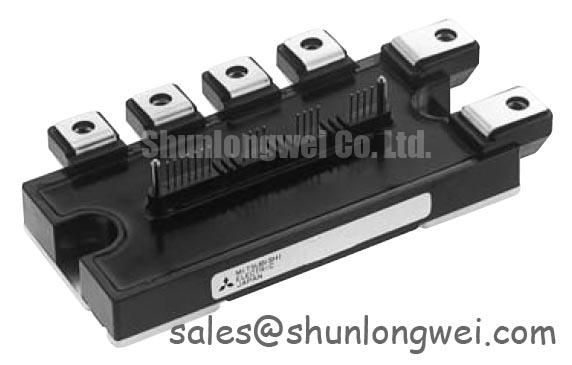
Before fitting a replacement, isolate the converter, inspect the heatsink contact face, and verify that the unit identification matches PM50B4LB060 and the specified 600V voltage rating. This Mitsubishi Electric intelligent power module is specified with a 50A collector-current rating, an integrated H bridge arrangement, and built-in gate drive, short-circuit, overtemperature, and undervoltage protection functions. These official specifications make it relevant for controlled power stages where a compact protected switching assembly is required.
| Official Specification | Value | Integration Relevance |
|---|---|---|
| Manufacturer | Mitsubishi Electric | Original device manufacturer identification |
| Model | PM50B4LB060 | Intelligent power module reference |
| Collector-Emitter Voltage | 600V | Specified VCES rating |
| Collector Current | 50A | Specified IC rating under the applicable datasheet conditions |
| Configuration | H Bridge | Four IGBT switching positions for reversible or single-phase power conversion |
| Isolation Rating | 2500V | Specified module isolation test rating; verify the applicable datasheet test conditions |
| Integrated Functions | Gate Drive, SC, OT, UV Protections | Integrated control and protective functions |
The PM50B4LB060 is rated at VCES = 600V and IC = 50A as official datasheet specifications. In a commercial string inverter or microgrid energy storage repair, those ratings should be checked against the original converter topology and measured DC-link conditions before the part is energized. The H-bridge architecture integrates four IGBTs for applications such as single-phase inverters, choppers, and bidirectional motor control. It does not remove the need to assess the surrounding DC-link capacitors, busbar joints, braking circuit, sensing circuit, and driver command path.
Design Consideration: switching overshoot is influenced by the product of commutation-loop inductance and the rate of current change. In practical terms, a long, asymmetrical, or loosely assembled busbar can add an inductive voltage component to the DC-link voltage during switching. A planar, closely coupled positive and negative busbar arrangement is commonly used to minimize loop inductance and help suppress turn-off overshoot. The final geometry, clearances, capacitor placement, and peak-voltage margin must be verified by the system engineer with appropriate switching measurements.
Where a film snubber capacitor is present in the original equipment, retain its intended electrical location close to the active commutation loop. Moving it to a remote terminal position can reduce its ability to control local transients. The capacitor type, capacitance, voltage rating, and connection method should be taken from the original converter documentation or a validated service design. A replacement IPM should not be used to justify arbitrary changes to the snubber network.
For field troubleshooting, inspect for discoloration around power terminals, loosened busbar hardware, damaged insulation barriers, and signs that the DC-link capacitor terminals have been mechanically stressed. With power removed and stored energy safely discharged, compare the physical busbar routing with a known-good assembly. If a repaired inverter shows intermittent protection events under load, capture switching waveforms only with suitably rated differential measurement equipment and evaluate the result against the original power-stage behavior.
⚠️ Maintenance Note: Periodically monitor terminal contact temperature rise and confirm that heatsink airflow passages remain clear of dust before seasonal high-load operation.
Transient Dynamics and Environmental Derating for PM50B4LB060
High-elevation installation, ambient temperature, enclosure contamination, humidity cycling, and DC-link quality all require system-level assessment. No official FIT rate, cosmic-ray failure rate, single-event burnout limit, altitude rating, or service-life figure is stated in the supplied PM50B4LB060 specifications. It would therefore be inappropriate to assign a numerical failure prediction or a fixed high-altitude derating rule to this model.
Design Consideration: terrestrial neutron exposure and voltage-related semiconductor stress are topics that may matter in systems deployed at elevated locations, but the applicable evaluation depends on the converter DC bus, switching conditions, enclosure environment, mission profile, and validated qualification evidence. Engineers responsible for commercial string inverter and microgrid energy storage equipment should review the complete system specification and applicable manufacturer documentation rather than infer an altitude capability from the IPM voltage rating alone.
The immediate repair priority is usually more measurable. Verify the DC-link voltage during startup, normal conversion, load transients, and controlled shutdown. Check that the original capacitor bank is correctly connected, that busbar joints are clean and secure, and that the command logic cannot issue an unintended switching state during controller reset. A protection response may result from a range of conditions, including supply instability, incorrect control sequencing, load abnormalities, thermal conditions, or a degraded connection. Oscilloscope evidence and comparison with the known-good signal path are more reliable than assigning a single cause from a fault indication.
The PM50B4LB060 includes gate drive and SC, OT, and UV protections as official datasheet specifications. These integrated functions can simplify the surrounding implementation, but they should be treated as part of the complete protection chain rather than the sole safeguard for an energy storage inverter. When evaluating newer power conversion architectures or different switching technologies, the technical context in Wide Bandgap Revolution can help frame the distinct design challenges of GaN and SiC devices. Such technology comparisons do not establish a direct replacement relationship for this Mitsubishi Electric IPM.
Assembly Integrity and Control Return Routing Around PM50B4LB060
The 2500V isolation rating is a specified module insulation test rating. This value should be understood within the module’s specified insulation structure and test conditions and must not be extended into a claim about complete equipment insulation coordination, enclosure safety approval, or system EMC compliance. The complete converter still requires appropriate creepage, clearance, grounding, shielding, and protective-earth decisions determined by the equipment design.
During installation, clean the heatsink mounting face and inspect it for burrs, corrosion, flatness issues, or trapped debris. Apply thermal interface material in accordance with the original equipment service procedure and use the specified fasteners and tightening sequence. Design Consideration: even contact pressure across the module base helps the thermal interface perform consistently, while uneven mounting can produce localized thermal stress or unstable temperature readings. The correct mounting torque must be taken from the original module documentation and the equipment mechanical drawing.
Control wiring deserves the same attention as the power path. Keep logic and sensing connections away from high-current commutation loops where practical, and preserve the original return routing. If the application uses separate control-reference and power-return paths, do not combine or reroute them without checking the manufacturer pin assignment and the original circuit design. Incorrect return routing can couple switching noise into the control reference and may lead to irregular gating, false protection activity, or waveform ringing.
The integrated gate-drive function does not authorize assumptions about external control-supply requirements, pin functions, logic thresholds, or startup timing. The system integrator should verify these details from the original panel documentation and the applicable Mitsubishi Electric documentation. For bootstrap supply arrangements in related DIPIPM implementations, Mitsubishi Electric’s DIPIPM Bootstrap Circuit Design reference provides useful general circuit context. It should not replace confirmation of the PM50B4LB060 pinout and application conditions.
In a maintenance program, inspect cooling fans, filters, heatsink fins, connector retention, control-cable strain relief, and terminal tightness at intervals appropriate to the equipment duty cycle. Condensation risk also deserves attention where a cabinet experiences temperature swings. Dry, clean interfaces and intact enclosure seals support stable operation, but the required inspection interval remains a site- and system-determined decision.
Preventing Spurious Faults During Bidirectional Power Flow with PM50B4LB060
The H-bridge configuration of the PM50B4LB060 supports evaluation for controlled bidirectional switching arrangements, subject to the actual schematic, control firmware, and operating conditions. In commercial string inverters and microgrid energy storage equipment, bidirectional energy transfer can expose the power stage to repeated transitions between charging, discharge, reactive-power support, and protective-shutdown states. The module’s integrated SC, OT, and UV protection functions are relevant to robust control implementation, yet the response of the complete assembly depends on the external sensing, command logic, DC source, load, and thermal system.
When a converter includes regenerative braking or an energy-dissipation path, confirm whether the original system uses a braking chopper and resistor, a battery charge-acceptance path, or another controlled energy destination. A braking resistor is a system component that converts excess electrical energy into heat. Its resistance, pulse capability, cooling arrangement, and controller thresholds must be retained or validated at equipment level. They cannot be derived from the PM50B4LB060 current rating alone.
Repeated power-direction changes can create cyclic thermal loading in the semiconductor assembly, thermal interface, heatsink, and busbar joints. Design Consideration: stable cooling airflow, clean heatsink fins, proper interface-material condition, and sound electrical terminations reduce avoidable thermal variability. Where a protection event occurs only after sustained cycling, record the command state, DC-link behavior, module temperature indication, airflow condition, and load profile before replacing parts. This record helps distinguish a power-stage concern from a control, cooling, or external-load issue.
A cross-model comparison must begin with topology, voltage class, current requirement, control interface, isolation requirements, mechanical footprint, and protection behavior. The CM300DXDX1-24A is a separate power semiconductor product that may be reviewed for specification comparison, but it should not be considered a direct substitute without a complete engineering assessment. Mitsubishi Electric also provides broader information on SiC power modules and SBDs for teams reviewing power semiconductor technology options at system level.