


Content last revised on March 28, 2026
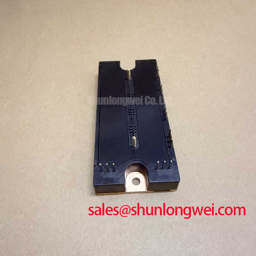
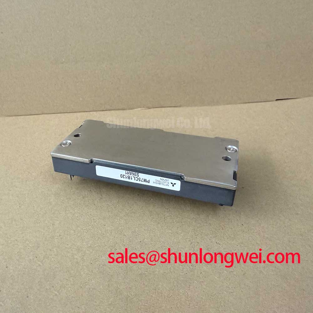
PM75CL1B120 Datasheet | 1200V 75A IGBT for Efficient Drives
Engineered for High-Efficiency Power Conversion
The Mitsubishi PM75CL1B120, an L1-Series Intelligent Power Module (IPM), leverages advanced CSTBT™ technology to deliver exceptional efficiency in high-frequency power conversion systems. This module integrates a complete 7-in-1 topology for three-phase inverter applications, optimized to reduce system losses and simplify thermal management. With core specifications of 1200V | 75A | VCE(sat) 1.55V (typ.), it provides a foundation for robust and energy-conscious designs. Key benefits include substantially reduced power losses and a more straightforward thermal design path. For engineers wondering how CSTBT™ impacts their design, it directly lowers the collector-emitter saturation voltage (VCEsat), which diminishes conduction losses and enhances the thermal stability of the entire inverter assembly.
Decoding Key Parameters for Efficiency Modeling
Understanding the technical specifications of the PM75CL1B120 is fundamental to leveraging its full potential. The following table breaks down critical parameters, translating them into their direct engineering significance for your design process.
| Parameter | Value | Engineering Significance |
|---|---|---|
| Collector-Emitter Saturation Voltage (VCE(sat)) | 1.55V (typ) at Ic=75A, Tj=125°C | This value directly quantifies conduction losses. Think of VCE(sat) as the 'toll' the current pays to pass through the switch; a lower toll, like the 1.55V of this module, means less energy is wasted as heat, directly improving system efficiency and easing heatsink requirements. |
| Total Switching Energy (Eon + Eoff) | 15.0 mJ (typ) at 600V, 75A, 150°C | Represents the energy lost each time the IGBT turns on and off. The defined switching energy allows for precise calculation of switching losses, which is critical for applications operating at higher frequencies, such as advanced motor drives and power supplies. |
| Junction-to-Case Thermal Resistance (Rth(j-c)Q) | 0.22 °C/W (max) per IGBT | This figure indicates how efficiently heat can be transferred from the IGBT chip to the module's baseplate. A lower value signifies superior heat dissipation, enabling higher power density and enhancing the long-term reliability of the power stage. |
For detailed electrical and thermal characteristics, download the official PM75CL1B120 datasheet.
Frequently Asked Questions on the PM75CL1B120
- What is the primary benefit of the CSTBT™ technology in the PM75CL1B120?
The Carrier Stored Trench-gate Bipolar Transistor (CSTBT™) technology significantly reduces the on-state voltage drop (VCE(sat)) compared to conventional IGBTs. This results in lower conduction losses, which enhances overall energy efficiency and reduces the thermal load on the system. - Does the PM75CL1B120 include integrated gate drive components?
Yes, as an Intelligent Power Module (IPM), it integrates control circuits including bootstrap diodes and current-limiting resistors for the high-side gate drivers. This integration simplifies the gate drive circuit design, reducing external component count and board complexity. - How can I accurately model thermal performance for this module?
To model thermal performance, use the Rth(j-c) values provided in the datasheet to calculate the temperature rise from junction to case. This, combined with the thermal resistance of your chosen heatsink (Rth(c-f) + Rth(f-a)), allows you to predict the operating junction temperature based on calculated power losses (conduction + switching). For a deeper understanding, review resources on IGBT thermal performance. - What is a "7-pack" configuration in an IGBT module?
A 7-pack or "CIB" (Converter, Inverter, Brake) module integrates a three-phase inverter bridge (six IGBTs and six diodes), a brake chopper (one IGBT and one diode), and sometimes a three-phase diode bridge rectifier into a single package. The PM75CL1B120 is a 7-in-1 module containing the inverter and brake chopper stages. - What is the short-circuit withstand time (tsc) for this module?
The PM75CL1B120 specifies a short-circuit protection trip level and a delay time, but the minimum withstand time is typically defined for Vcc up to 800V and Tj at 150°C. The module includes integrated short-circuit protection that sends a fault signal (Fo) and safely shuts down the device. Always refer to the SCSOA curves in the datasheet for precise limits.
A Technical Dissection of the CSTBT™-Powered PM75CL1B120
The performance of the PM75CL1B120 is rooted in its 5th generation Mitsubishi Electric CSTBT™ chip technology. This structure introduces a carrier storage layer beneath the trench gate, which modifies the electron and hole distribution within the device during conduction. The result is a significant reduction in the on-state voltage (VCE(sat)) without a prohibitive trade-off in switching speed. What defines its low conduction loss? A typical VCE(sat) of just 1.55V at its nominal 75A current rating. This characteristic is crucial because, in many motor drive applications, the device spends most of its time in the 'on' state, making conduction losses a dominant factor in overall system inefficiency. By minimizing these static losses, the PM75CL1B120 directly contributes to a lower total power loss, enabling more compact and cost-effective cooling solutions. Further details on IGBT structure can be explored in our guide to deconstructing the IGBT.
Gaining a Competitive Edge: Efficiency in Modern Power Systems
In today's industrial landscape, energy efficiency is not just an operational benefit but a strategic imperative. Regulations and market demands continually push for systems with lower power consumption. The PM75CL1B120 directly addresses this trend. Its low-loss characteristics, enabled by the CSTBT™ technology, allow designers of Variable Frequency Drives (VFDs) and servo systems to achieve higher efficiency ratings. This translates into a lower Total Cost of Ownership (TCO) for the end-user through reduced energy bills. Furthermore, the integrated protection features—including short-circuit, over-temperature, and under-voltage lockout—enhance system reliability, reducing downtime and maintenance costs, which are critical metrics in industrial automation and renewable energy infrastructure.
Data-Centric Comparison for System Architecture Decisions
To support informed engineering decisions, it is essential to evaluate components based on datasheet facts. The PM75CL1B120 presents a specific performance profile. When designing a power stage, engineers may consider various modules. For systems requiring similar specifications, the PM75CL1A120 is another available option. For applications demanding higher current handling, a module like the PM100CSD120, rated at 100A, could be evaluated. The selection process should be guided by a thorough analysis of the trade-offs between electrical performance, thermal characteristics, and physical footprint as detailed in the respective datasheets. For inverter designs up to ~30kW targeting high efficiency, the PM75CL1B120's low VCE(sat) of 1.55V presents a clear advantage.
Where Efficiency Matters: PM75CL1B120 Application Focus
The feature set of the PM75CL1B120 makes it exceptionally well-suited for a range of power conversion applications where efficiency and reliability are paramount.
- Industrial Motor Drives: In VFDs, the module's low VCE(sat) and integrated 7-pack topology reduce overall power dissipation and simplify the inverter design, contributing to more compact and efficient motor control systems. What makes it ideal for VFDs? Its 7-pack topology integrates a three-phase inverter and brake chopper.
- Servo Drives: For high-precision robotic and CNC servo drives, the module's fast and clean switching characteristics, aided by integrated protection and control logic, enable precise current control and dynamic motion profiles.
- Uninterruptible Power Supplies (UPS): The module's high reliability and integrated protection circuits are critical for UPS systems, ensuring dependable power delivery during grid failures.
- Renewable Energy Inverters: In solar and small-scale wind applications, maximizing energy harvest is key. The high conversion efficiency of the PM75CL1B120 helps to minimize power losses, converting more of the generated DC power into usable AC power.
From Theory to Practice: Deployment Insights
The thoughtful design of the PM75CL1B120 extends to its practical implementation, offering features that streamline the assembly and enhance the robustness of the final system.
- Simplified Gate Drive: The integration of bootstrap diodes and resistors within the module reduces the bill of materials and complexity of the high-side gate driver circuit.
- Integrated Protection: On-chip over-temperature, short-circuit, and supply under-voltage protection provide a robust safety net, reducing the need for extensive external monitoring circuitry and accelerating development time.
- Optimized Thermal Interface: The flat-base package is designed for a low-resistance thermal connection to a heatsink, a crucial factor for long-term reliability under demanding load cycles.
A Designer’s Outlook: Enabling Future Advancements
Adopting a module like the PM75CL1B120 is more than a component choice; it's a strategic decision that shapes future design possibilities. The superior efficiency and thermal performance grant engineers valuable headroom. This can be leveraged to either increase the power density of the next product generation within the same physical footprint or to significantly reduce the size, weight, and cost of the cooling system for a more competitive design. By abstracting away complex protection and drive circuitry, this Intelligent Power Module allows design teams to concentrate their efforts on higher-level system innovation, such as advanced control algorithms and enhanced user-facing features, ultimately accelerating the path to market for more sophisticated and reliable power electronic systems.