

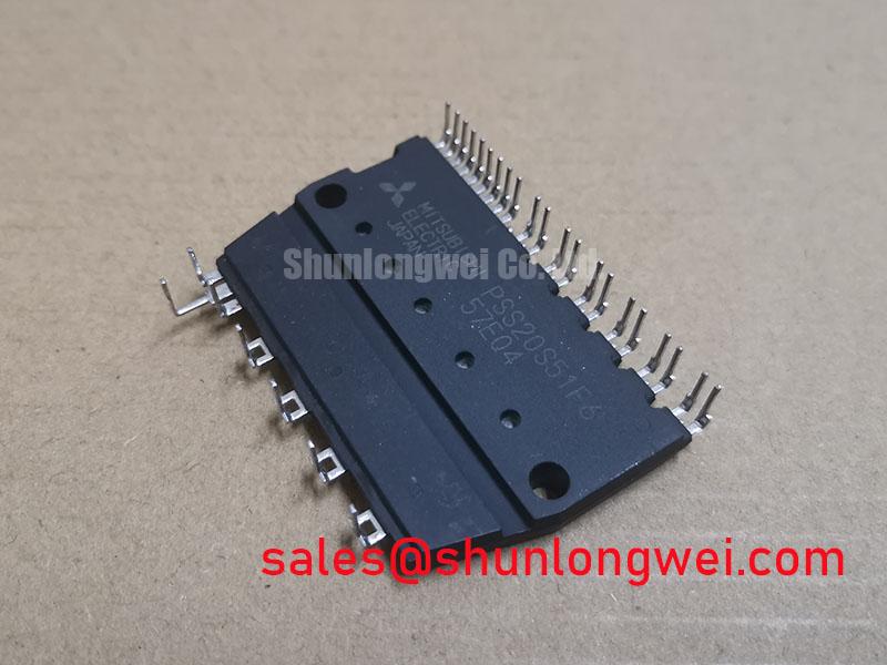


Content last revised on October 1, 2026
Assembly Integrity and Layout Architecture for Short-Circuit Protection
| Manufacturer | StarPower |
|---|---|
| Model | PSS20S51F6 |
| Product category | IGBT Module |
| Package | Power Module |
Probe the gate to emitter and collector to emitter waveforms during a controlled fault test, then compare the measured turn-off response with the protection timing required by the inverter control board. For PSS20S51F6, short circuit protection remains a system-level design responsibility; the module specification supplied here does not define a guaranteed short circuit safe operating area, detection delay, or withstand duration.
A practical design consideration is to detect both rapid desaturation and abnormal collector voltage rise, because a single threshold can miss faults during commutation or severe switching noise. If the protection objective is detection within 10 microseconds, the designer should validate the complete signal path, including sensor delay, comparator response, gate driver propagation, and the turn-off profile. Two-stage soft turn-off can reduce the rate of current collapse before the final gate shutdown, but its timing and gate impedance must be verified against the measured inductive overshoot.
Keep the high-current commutation loop compact and route the gate-return path separately from the power return path. Gate-driver reference connections should follow the actual emitter potential at the module terminals rather than a distant control ground. Oscilloscope measurements should use an appropriate differential probe and a known-good switching waveform. Unexpected ringing may indicate parasitic inductance, probe-loop pickup, an imbalanced gate path, or a protection circuit that is reacting too late.
For a replacement assessment, compare terminal identity, mechanical mounting, electrical ratings, driver requirements, and protection behavior rather than relying on package appearance alone. A neutral compatibility review may also include FF400R33KF2 when the original equipment documentation identifies a compatible electrical and mechanical arrangement.
Transient Dynamics and Electrical Design at Elevated Installation Altitude
Record the DC-link voltage, switching overshoot, and fault-clearing waveform at the actual installation location before assigning a high-altitude derating value to PSS20S51F6. Terrestrial neutron exposure and cosmic-ray-related single-event effects are application-dependent reliability subjects, and no FIT rate, SEB threshold, or altitude lifetime value is established by the supplied product data.
Above approximately 2000 m, altitude should be treated as a design consideration affecting insulation coordination, cooling, ambient pressure, and the statistical exposure environment. Engineers should obtain a qualified manufacturer or standards-based reliability source before converting those factors into a numerical SEB prediction. DC-bus headroom should be verified from measured switching peaks, transient suppression behavior, and the complete operating envelope rather than from a generic percentage margin.
Coordinate any high-speed semiconductor fuse with the module's documented surge and fault ratings, the DC-link capacitance, and the actual prospective short-circuit current. Fuse I²t coordination is an engineering calculation that must include cable inductance, fuse clearing characteristics, and the controller's gate-shutdown delay. A fuse that clears quickly may still allow a damaging local transient if the commutation loop produces excessive voltage during current interruption.
For power-stage topology reviews, the 2MBI100U4H-170 can be evaluated as a related IGBT module when its voltage, current, package, and gate-drive requirements match the original circuit. The relationship should be confirmed from the complete schematic and not assumed from product category alone.
Field Diagnostics and Commissioning of Thermal Feedback Topologies
Measure collector-emitter voltage, phase current, gate-emitter voltage, and heatsink temperature on each parallel path during the same load step, then compare the waveforms for timing and thermal divergence. The supplied data does not state a specific VCE(sat) value or current-sharing limit for PSS20S51F6, so measured behavior must be assessed against the applicable device documentation and system limits.
A positive temperature coefficient of on-state voltage can support static current sharing in a correctly matched parallel arrangement, but it does not guarantee dynamic balance during turn-on or turn-off. Designers should keep gate-loop geometry, driver impedance, emitter-return routing, and power-loop inductance as symmetrical as the mechanical layout permits. A current imbalance may result from gate timing, stray inductance, thermal contact, sensor placement, or unequal conductor resistance; verify each possibility with synchronized waveforms.
During commissioning, check the gate signal at the module terminals rather than only at the driver output. Confirm that the turn-off bias remains controlled during common-mode voltage transitions and that the control-ground reference is not moving with the power return. For a commercial string inverter or microgrid storage converter, also review DC-link energy absorption paths, because abnormal bus recovery can expose the IGBT to a transient unrelated to steady-state load current.
The assembly's temperature feedback path should be checked together with its cooling system. Where an NTC thermistor is used in the surrounding thermal monitoring arrangement, its resistance-temperature behavior should be interpreted according to the selected sensor documentation; general thermistor principles are described by this technical reference. The ROHM IGBT resource provides useful industry background on switching-device behavior, but it does not define StarPower-specific limits.
PSS20S51F6 Thermal-Electrical Optimization at the Heatsink Interface
Inspect the heatsink contact pattern, baseplate seating, thermal interface spread, and screw sequence when measured junction-related temperature rises unexpectedly under a stable load. The supplied product data identifies the package as a Power Module but does not provide a module-specific mounting torque, baseplate flatness tolerance, or thermal resistance value.
Use the thermal interface material specified for the assembly and control its application consistently across the contact surface. A 50 to 100 micrometre interface layer may be used only as a general installation starting point when supported by the selected material and surface condition; it is not an official PSS20S51F6 specification. Excess compound can increase thermal resistance, while incomplete coverage can create localized hot regions.
Check for baseplate curvature, burrs, contamination, and uneven heatsink contact before tightening the assembly. A sequential cross-pattern installation is a design consideration that helps distribute contact pressure, but the final torque must come from the module documentation, fastener grade, thread condition, and heatsink construction. Recheck terminal tightness and thermal readings after the equipment has completed representative load cycling.
Maintenance Note: Schedule heatsink cleaning, inspect thermal-interface ageing, and monitor contact temperature trends before increased temperature becomes an intermittent inverter shutdown.
For long-life evaluation, record load current, switching frequency, heatsink temperature, ambient conditions, and fault history as a matched dataset. The IGBT technical knowledge base can support broader device-physics review, while the final acceptance decision should remain tied to measured system performance and the applicable StarPower documentation.