

Content last revised on October 11, 2026
PM300RL1A060-202G Thermal-Electrical Optimization: Floating Gate Bias Supply Decoupling Practical Tuning
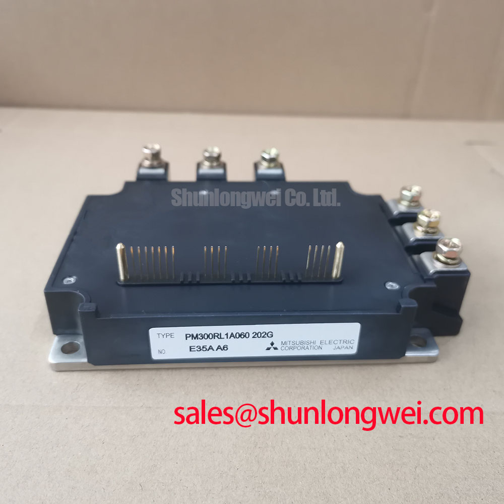
I check the auxiliary supply at its local control reference before allowing the DC link to energize. For the PM300RL1A060-202G, the first task is to establish whether the existing control board delivers the supply sequence and command states required by the module interface. An IPM must not be treated as a bare IGBT with an externally accessible gate. Applying a separate negative gate supply without establishing that interface can create an incompatible connection rather than improve turn-off behavior.
Design Consideration: Observe auxiliary voltage during startup, switching enable, and shutdown, not just with the controller idle. A supply that appears stable on a multimeter can dip when its driver circuitry becomes active. Use a suitably rated differential or isolated measurement arrangement, with the reference connected to the appropriate control return. Compare the supply waveform with enable commands and fault feedback to determine whether a supply disturbance precedes the protection event.
Local decoupling should support the driver supply without sharing a long, noisy return path with switching power current. As an engineering recommendation, inspect capacitor connections, solder joints, connector resistance, and the route between the auxiliary source and module interface. Component selection and placement belong to the original supply design: capacitance alone does not establish adequate transient performance when connection inductance or source impedance dominates.
Undervoltage protection also needs a sequencing check. Where the interface provides fault feedback, the controller should maintain its intended safe state while auxiliary power settles and during supply collapse. Verify that behavior against the machine schematic and applicable module timing requirements. Do not infer a protection threshold or recovery delay from the 600.0 V and 300.0 A ratings; those ratings describe different electrical boundaries.
The Mitsubishi DIPIPM™ Bootstrap Circuit Design note provides useful background on supply charging and operating conditions for bootstrap-powered circuits. Its DIPIPM-specific arrangements are not a wiring prescription for this module. For repair evaluation, the practical distinction is between understanding a supply mechanism and transferring another product family’s circuit to the installed hardware.
For controller-side signal integrity, Precision Gate Drive Design offers complementary gate-drive context. Apply that discussion at the accessible interface: establish stable supply references and valid control commands before interpreting switching disturbances as evidence of a defective power stage.
PM300RL1A060-202G Thermal-Electrical Optimization: Suppression of 2x V_DC Voltage Doubling at Practical Tuning
Measure the switching waveform at both the converter output and the remote load when cable-related overvoltage is suspected. A peak at the load terminals is not automatically the voltage across the module’s switching devices. Separating those measurement locations prevents a reflected-wave problem from being confused with local commutation overshoot.
Design Consideration: A long cable behaves as a transmission line when switching edges are fast relative to its propagation time. A large mismatch between cable characteristic impedance and load impedance can produce a reflected voltage approaching twice the incident step in the ideal open-ended case. That is a general transmission-line result, not a guaranteed operating waveform or an additional voltage capability of the PM300RL1A060-202G. Actual peaks depend on the load, edge shape, cable losses, and repeated reflections.
Record cable configuration, load condition, switching command, and probe location with each capture. Use probes whose voltage rating, common-mode performance, and bandwidth suit the measurement. A long probe connection can add apparent ringing, while insufficient bandwidth can conceal the peak being investigated. Compare traces under controlled conditions before changing the filter or attributing the disturbance to the module.
Output reactors and dv/dt filters should be evaluated against the measured edge behavior and the connected load. As an engineering recommendation, select their impedance, damping, thermal capacity, and insulation requirements at system level. A filter that reduces a remote terminal peak can still change converter current, introduce resonance, or increase dissipation. Its suitability therefore depends on switching tests and load operation, not simply on matching the module’s current rating.
Local switching overshoot requires a different inspection. Freewheeling-diode recovery, commutation-loop inductance, and switching speed can interact to produce ringing near the power module. Review DC-link capacitor placement, bus connections, and the existing snubber network. Avoid assigning a particular reverse-recovery characteristic to this model without its corresponding device curves. Snubber changes should be assessed for both peak suppression and the additional energy dissipated during operation.
Where the equipment already uses a metal-oxide varistor network, check its coordination with the protected circuit and other suppression components. A MOV is not a substitute for controlling a repetitive high-frequency commutation loop. Reduced waveform ringing may help electromagnetic performance, but it does not establish equipment EMC compliance. Mitsubishi’s Power Semiconductors & High-Power Modules resources provide manufacturer context for device-family documentation and application guidance.
Assembly Integrity & Layout Architecture: Implementing PCB Gate Loop Layout Symmetry for PM300RL1A060-202G
Trace the control return separately from the main current path before revising PCB routing around the module. Shared return impedance can move the apparent control reference during switching, even when the controller output itself remains clean. For this IPM, inspect the documented external terminals rather than assuming that a discrete-device gate or Kelvin-emitter connection is available.
Design Consideration: Where the documented interface provides separate control-reference connections, preserve their intended separation from high-current conductors. Keep related command and return paths close enough to limit loop area, while maintaining the clearance and creepage required by the equipment’s voltage and insulation design. Geometrical symmetry is useful only when it also preserves the correct electrical references; matching trace lengths cannot compensate for an incorrectly shared return.
Compare command waveforms at the controller and at the module interface if switching disturbances correlate with erratic operation. Look for reference movement, coupled spikes, and supply disturbance before changing command conditioning. Collector-voltage transitions can couple through an IGBT’s reverse-transfer capacitance, contributing to unintended gate movement. For an IPM, that mechanism does not establish access to the internal gate or justify adding an external Miller clamp to a control input. Any damping or clamp change must suit the actual interface.
Mechanical assembly deserves the same attention as routing. Inspect the mounting surface for contamination, damage, and uneven contact. As an engineering recommendation, apply the specified thermal interface material consistently and follow the applicable mounting sequence and torque. Excess material, incomplete coverage, or uneven fastening can impair heat transfer; no universal film thickness or bolt torque should be assigned to this package from its electrical ratings.
Field Alert: Keep the DC link isolated and verify discharge before handling module terminals, and use the specified mounting procedure rather than a generic bolt-torque value.
For thermal assessment, distinguish case temperature from junction temperature. Transient thermal impedance is relevant when current pulses or changing duty cycles produce short-duration heating that a case sensor cannot track directly. Use the applicable thermal curves with the actual loss waveform and cooling arrangement; a steady-state heatsink reading alone does not establish pulse-temperature margin.
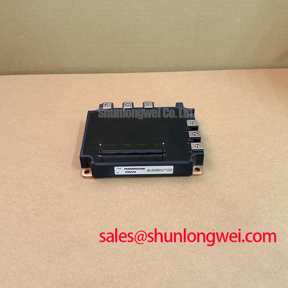
In replacement evaluation, PM75CSD120 is another Mitsubishi module to review as a separate candidate, not an established direct substitute. Compare topology, terminal arrangement, control interface, package dimensions, and thermal conditions before considering substitution. Engineers evaluating an industrial inverter welder or medium-frequency induction-heating power stage should also compare the original switching duty and protection arrangement. Matching manufacturer names or a single headline rating does not establish compatibility.
PM300RL1A060-202G Operational Boundaries: Evaluating Regenerative DC-Bus Voltage Surge Dissipation Limits
Capture DC-bus voltage through the operating event that triggers the shutdown, then identify where returned energy is intended to go. If a motor-driven system regenerates during deceleration, the relevant checks include its braking path, bus capacitance, and controller response. In another load topology, the source of rising bus voltage may differ, so establish the energy path from the schematic before diagnosing the module.
Design Consideration: A braking circuit must be evaluated as a coordinated switch, resistor, control, and thermal assembly. Do not assume that the PM300RL1A060-202G contains an accessible braking IGBT from its model designation alone. Determine whether the installed equipment uses a documented internal function or a separate switching stage, then examine that stage’s command signal, current path, and protection response.
For a resistor-based braking arrangement, assess pulse energy, repetitive loading, cooling, and the permitted duty cycle together. A resistance measurement can reveal an open circuit or a substantial change from the component specification, but it cannot establish the resistor’s ability to absorb an operating energy pulse. Inspect connections and thermal protection, and compare the observed bus rise with the braking command to distinguish an absent command from an ineffective discharge path.
The module’s 600.0 V rating is an electrical boundary, not a braking-controller setpoint. Coordination should account for the highest bus voltage together with local switching overshoot and the limits of every component on that bus. Similarly, an overvoltage suppression device should be checked against its clamping behavior and energy duty. Continuous or repeated regenerative energy requires an intended absorption or recovery path rather than reliance on a surge absorber alone.
When reviewing neighboring power stages, PM150RLA120 can be considered as a separate Mitsubishi IPM reference. Its role in a front-end or auxiliary stage must follow the equipment schematic and its own specifications; it should not be described as a rectifier or compatible braking component solely because it belongs to the same manufacturer’s module range.
After correcting the identified path, test the relevant operating transition under controlled conditions while recording bus voltage, braking command, and thermal behavior. Compare the resulting waveforms with the equipment’s specified limits, including the switching peaks at the module terminals. If the bus still rises before the discharge path becomes effective, investigate command timing and path continuity rather than replacing the power module on the symptom alone.