

Content last revised on September 24, 2026
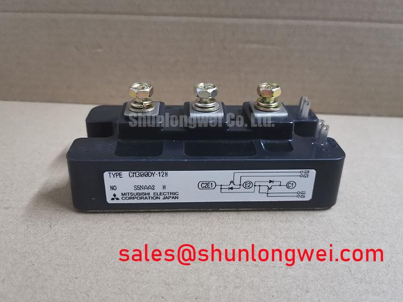
Benchtop Waveform Tuning: Mitigating Stress via Optocoupler vs Digital Coreless Transformer on CM300DY-12HE
Before connecting a replacement CM300DY-12HE to the live DC bus, inspect the gate-driver isolation path as a complete circuit. In a traction inverter, a driver based on an optocoupler and one based on a digital isolated architecture can behave differently during fast collector voltage transitions. The important question is not which isolation method is universally better; it is whether the installed driver maintains a valid gate command when the switching node moves rapidly.
Design Consideration: verify the galvanic isolation capability, common-mode transient behavior, creepage distance, clearance, and supply-to-output isolation of the actual gate-driver assembly. These values belong to the gate-driver datasheet and the inverter safety design, not to the CM300DY-12HE module rating. Route the gate command and its return path as a closely coupled loop, separated from high-current power paths. If the module package documentation identifies an auxiliary emitter terminal, use its intended low-current reference path for the driver return rather than sharing the power emitter path. Do not assume that every module or inverter board provides that terminal.
During a controlled waveform check, probe the gate-to-emitter voltage at the module connection rather than only at the driver output connector. A clean command at the controller can still arrive distorted at the module because of trace inductance, connector resistance, or return-path noise. Unwanted gate movement during the opposite switch transition may indicate coupling through the gate network, an inadequate driver return layout, or a degraded isolation-stage supply. Compare the suspect phase with a known-good phase where practical and preserve the original probe reference method.
⚠️ Field Alert: Disconnect and verify discharge of the DC bus before moving oscilloscope grounds, changing gate-drive wiring, or tightening module terminals.
For wider integration context, Mitsubishi Electric provides an industry reference on power semiconductors and high-power modules; the installed equipment schematic and the applicable module documentation remain the controlling references for terminal use and drive conditions.
Transient Dynamics & Electrical Design: Dynamic Gate Impedance Control for Robust CM300DY-12HE Operation
Gate impedance is a system-level tuning element, not a fixed attribute of the 600V 300A module. In field repair work, retain the original gate resistor network, diode paths, clamp components, and driver layout unless the equipment manufacturer’s circuit documentation authorizes a change. Replacing a failed IGBT module while changing gate damping at the same time makes later fault isolation much harder.
Engineering Recommendation: use separate turn-on and turn-off control paths when the original driver architecture provides them, then verify switching waveforms under the actual DC-link and load conditions. Gate turn-off behavior deserves particular attention because parasitic inductance can raise collector-emitter voltage during current interruption. Minimize the commutation-loop inductance to suppress inductive overshoot, then verify peak voltage margin against the DC-link voltage during controlled switching tests. A negative gate bias and an active Miller clamp can be useful protection methods where the installed driver supports them, but the appropriate settings must be established by the system designer and confirmed against the driver and module documentation.
For parallel power paths, current sharing cannot be inferred from the nominal current marking alone. The temperature behavior of on-state voltage can assist stable sharing under suitable conditions, yet busbar symmetry, thermal contact, gate-loop symmetry, and switching timing remain decisive. Measure each branch under representative load instead of assuming equal current from physical proximity. An imbalanced waveform may point to unequal connection resistance, differing gate paths, thermal variation, or a problem in the controller’s phase command.
The anti-parallel diode behavior also affects inverter noise and stress. Reverse-recovery behavior, including recovery softness, interacts with commutation inductance and gate turn-on speed. A sharp recovery event may aggravate ringing and radiated noise, while a slower transition can increase switching loss. This is a Design Consideration requiring measurement in the finished power stage, not a published CM300DY-12HE performance claim without the applicable test conditions.
When an equipment repair requires comparison with another Mitsubishi Electric module, CM300DXDX1-24A should be evaluated only against the original circuit requirements, package drawing, control interface, thermal arrangement, and rated operating conditions. Matching a current figure alone is not sufficient for an in-place substitution decision.
Benchtop Waveform Tuning: Mitigating Stress via Regenerative DC-Bus Voltage Surge Dissipation on CM300DY-12HE
Regenerative bus rise is often encountered when a traction motor decelerates, reverses, or is driven by an overhauling load. In forklift low-voltage traction systems, the energy path may include the battery, charger interface, DC-link capacitors, braking circuit, and controller logic. The CM300DY-12HE must be assessed as part of that path, because its official 600V rating does not define the bus-voltage behavior of the complete vehicle inverter.
Start fault tracing by logging the DC-link waveform during the event that causes shutdown, preferably with the same battery state, load condition, and command sequence that reproduces the issue. A rising bus voltage can be associated with regenerative energy, poor capacitor connection, a braking-control issue, unexpected load behavior, or measurement setup limitations. Check the braking command, associated switching device, ballast resistor connection, and feedback signal against the controller documentation before attributing the fault to the main IGBT module.
Design Consideration: a braking transistor and its resistor network must be selected from the expected regenerative energy, duty cycle, resistor thermal capability, wiring layout, and the control strategy of the specific system. The installer should verify that the braking path has adequate clearance from sensitive gate-drive wiring and that the current loop is compact enough to limit transient voltage disturbance. A resistor that is mechanically secure but thermally isolated from its intended heat path can create recurring trips without any visible defect in the CM300DY-12HE.
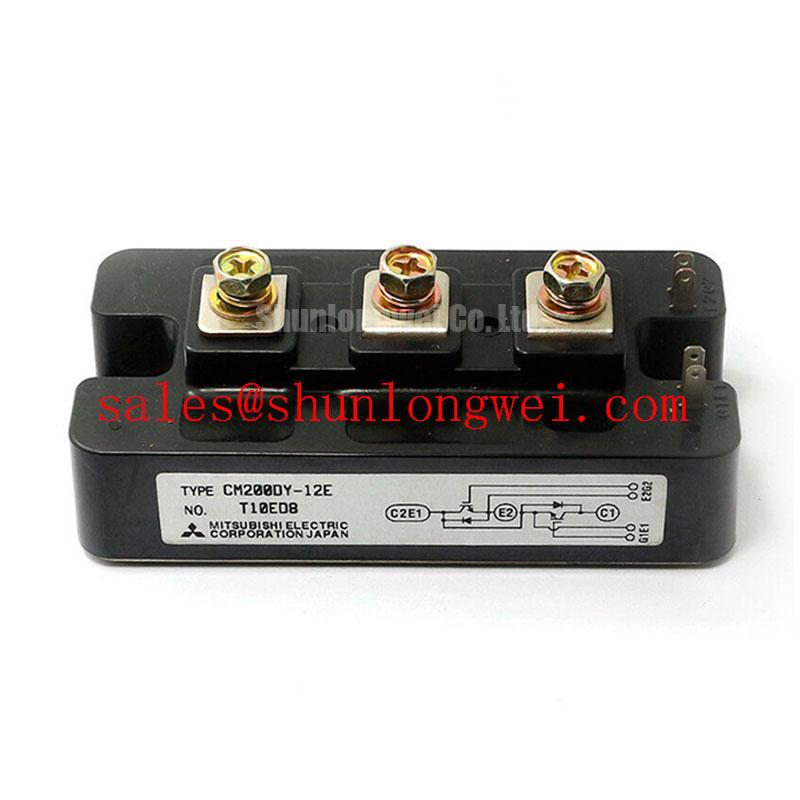
In multi-stage power assemblies, a smaller module can appear in a separate auxiliary or rectifier-related function rather than in the traction bridge itself. The CM100DY-12E is therefore best treated as a separately specified component for topology review, not as an assumed electrical replacement for the CM300DY-12HE.
Preventing Spurious Faults: High-Speed Fault Management: VCE Desaturation Guidelines for CM300DY-12HE
A desaturation circuit monitors the collector-emitter condition while the IGBT is commanded on. Its purpose is to identify an abnormal rise that can occur during overload, a short-circuit event, a gate-drive loss, or a connection fault. The protection threshold, blanking behavior, and fault response belong to the gate-driver and inverter design. They must not be copied from another controller simply because it uses a similarly rated module.
For a suspected false desaturation trip, inspect the sensing diode route, clamp parts, driver supply stability, gate-emitter reference, and noise coupling near the collector path. A desaturation event that appears only at switching transitions may indicate layout-related disturbance or an unsuitable protection timing relationship. Verify the signal with properly rated differential measurement equipment and compare it with the gate command, collector-emitter waveform, phase current, and DC-link voltage. This approach distinguishes a genuine power-stage fault from a corrupted protection signal more reliably than changing parts one at a time.
Engineering Recommendation: use a controlled soft turn-off response where the installed driver architecture supports it, because abrupt interruption of fault current can create additional voltage stress in a stray-inductive power loop. The response profile must be validated at system level against the module documentation, bus voltage, wiring geometry, and protection sequence. Type-specific short-circuit capability and safe operating area limits must be taken from the relevant Mitsubishi Electric datasheet rather than inferred from the 300A continuous current rating.
Maintain physical separation between desaturation sensing traces and noisy power-node conductors, and ensure that the driver return reference follows the intended emitter reference. If repeat failures occur after verified mechanical mounting and gate-drive checks, review the power-loop, gate-loop, thermal interface, and protection timing together. The practical design topics in IGBT Design & Integration can support that structured review while the original inverter documentation remains the final authority for repair configuration.