

Content last revised on September 28, 2026
SKM200GB12T4 Thermal and Electrical Optimization During Switching
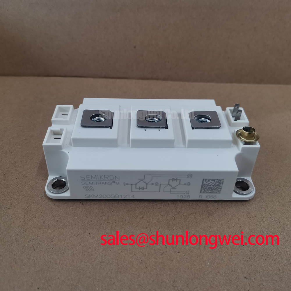
Start the bench check by isolating the drive, recording the original nameplate data, and inspecting the Semitrans housing of the SKM200GB12T4 for cracks, loosened terminals, contamination, or heat discoloration. Confirm that the replacement requirement matches the official ratings of 1200 V and 200 A before connecting any gate driver or DC link.
The SKM200GB12T4 is a Semikron IGBT module with an official voltage rating of 1200 V, an official current rating of 200 A, and a Semitrans package. These are the primary identity points for a repair engineer comparing a failed traction inverter module with the original assembly. They do not, by themselves, define the permissible switching frequency, short circuit duration, thermal impedance, or gate drive conditions. Those values must be verified from the applicable device documentation and the complete inverter design.
For an electric forklift or warehouse traction controller, begin with a cold state inspection rather than applying bus voltage immediately. Check the power terminals for uneven clamping, inspect the gate and auxiliary connections for damaged insulation, and compare the surrounding busbar geometry with the serviceable phase leg. A visual match is not enough if the replacement changes the current return path or the position of the gate driver connection.
Design Consideration: Short circuit protection should be coordinated with the actual driver delay, desaturation detection behavior, blanking interval, and the module’s specified short circuit safe operating area. Type I and Type II protection terminology is not a substitute for the manufacturer’s timing limits. A two stage soft turn off strategy may reduce the electrical stress produced when a faulted IGBT is forced off, but the final delay and gate current profile must be established by oscilloscope testing under the real DC link and load conditions.
During commissioning, monitor collector emitter voltage, gate emitter voltage, phase current, and the fault signal at the same time. An unexpected voltage overshoot can result from stray inductance, probe placement, commutation behavior, or an incorrectly referenced gate measurement. The troubleshooting decision should therefore be based on a known good waveform from the same topology, not on a single multimeter reading.
The external Semikron-Danfoss SEMITRANS® Industry Standard IGBTs product information provides useful manufacturer context for the package family. It should not be treated as a substitute for the specific electrical and thermal data applicable to the SKM200GB12T4.
Benchtop Waveform Tuning and Gate Loop Symmetry
When checking a repaired forklift traction inverter, keep the gate drive return path separate from the high current emitter path wherever the module connection structure permits it. The purpose is to prevent the voltage developed by load current flowing through common copper from appearing as an unintended gate emitter signal. This is a layout principle, not an SKM200GB12T4 factory guarantee.
At the bench, inspect the complete gate loop from driver output to gate terminal and back to the driver reference. Avoid routing this loop alongside the collector bus or the switching node for unnecessary distances. The auxiliary emitter return should be connected according to the module drawing and the driver topology. If the control return is accidentally tied into a high current section of the power emitter path, the waveform may show ringing, false turn on behavior, or an unstable apparent threshold.
Desaturation protection requires particular care. A desaturation circuit normally combines a sensing path, a blanking interval, a fault latch, and a controlled turn off sequence. The commonly discussed detection target of a few microseconds is a system design objective, not an official parameter established here for this module. Engineers should verify the actual detection timing against the driver data sheet, the diode and sensing network, and the measured collector emitter waveform.
A two stage soft turn off approach can be evaluated when a direct gate discharge produces excessive inductive voltage. The initial gate current reduction and the later turn off action should be tuned against the measured fault current and bus voltage. The correct values are system determined. Do not copy a gate resistor or negative gate voltage from another module without checking the SKM200GB12T4 documentation and the driver’s output capability.
For comparison work, the SKM100GB063D may be reviewed as a separate Semikron module, but its voltage, current, package details, gate behavior, and thermal limits must be evaluated independently. A lower rated or differently configured unit is not an automatic replacement for the SKM200GB12T4.
⚠️ Field Alert: Disconnect the DC link and verify the absence of stored energy before removing gate or power connections, then follow the original fastener and thermal interface procedure during reassembly.
Common Mode Current and Long Motor Lead Checks
Forklift traction systems can place the inverter close to the motor in one installation and several cable lengths away in another. Long motor leads can interact with cable impedance, motor terminal impedance, grounding, and switching edge speed. Reflections may increase terminal voltage and common mode current, but the actual magnitude cannot be assigned from cable length alone. The installation should be measured with suitable differential and common mode probes.
A practical field check begins with the motor cable shield or protective conductor, the inverter chassis bond, and the motor frame connection. Look for loose bonding points, paint under bonding surfaces, parallel routing with sensitive control wiring, and unplanned return paths through encoder or communication cables. A common mode current problem may also be confused with a gate drive fault, bearing current issue, or measurement artifact.
When the waveform suggests impedance mismatch, compare the inverter output directly at the module terminals with the waveform at the motor terminals. Use a measurement arrangement rated for the switching environment and verify probe common mode rejection. The commonly cited possibility of terminal spikes approaching twice the DC bus voltage is a transmission line effect that depends on the complete system; it is not a guaranteed characteristic of this module.
Output filters, common mode chokes, and dv/dt control networks should be selected from measured motor insulation stress, leakage current, switching behavior, and the drive manufacturer’s requirements. Designers should minimize parasitic loop area and verify peak voltage margins against the DC link during switching tests. Filter capacitance and choke impedance must be checked against inverter protection behavior because an unsuitable network can increase leakage current or affect current regulation.
The SKM200GB12T4 should not be described as independently compliant with a complete EMC standard. EMC performance belongs to the assembled drive, enclosure, cable system, grounding method, and test configuration. For broader technology context, engineers evaluating alternative switching platforms can consult the Wide Bandgap Revolution technical discussion, while keeping the present replacement decision tied to the specified Semikron IGBT module.
High dv/dt Cross Conduction and Protection Verification
False turn on during high dv/dt switching should be investigated by measuring both devices in the affected commutation leg, rather than assuming that the SKM200GB12T4 itself is defective. Review gate emitter voltage at the module terminals, driver supply stability, gate resistance, common emitter impedance, dead time, and the physical distance between the driver and power module. A driver waveform measured at its output pin may differ from the voltage reaching the module gate.
An active Miller clamp can help hold the inactive gate at a controlled state when the collector emitter transition couples through the device capacitances. Its suitability depends on the driver architecture, clamp current capability, gate resistance arrangement, and the module’s specified gate limits. A negative gate bias is sometimes used in high dv/dt applications, but the permitted value must come from the relevant device and driver documentation. The range of minus five to minus fifteen volts should not be treated as a default instruction for this model.
During a controlled low energy test, check whether the inactive gate develops a transient that coincides with abnormal phase current. Confirm the measurement reference directly at the module terminals and repeat the test with the intended busbar and motor cable arrangement. If the symptom disappears when the power layout is changed, the result may indicate parasitic coupling rather than a simple gate component failure.
Dead time, interlock logic, and fault reset behavior should be checked together. Excessive dead time can increase conduction loss, while insufficient dead time can reduce switching margin. The correct setting is determined by the complete driver, load current, temperature, and measured switching transitions. It should be validated over the expected operating range rather than selected from a generic IGBT rule.
Thyristor gate values such as gate trigger current and gate trigger voltage are not interchangeable with IGBT gate drive specifications. A pulse train used for a phase controlled rectifier must be assessed according to the thyristor data sheet and firing circuit. For the SKM200GB12T4, the relevant work is IGBT gate emitter control, desaturation response, commutation timing, and switching waveform verification. If the traction system includes a separate thyristor front end, its firing angle and harmonic mitigation remain system level functions and should not be assigned to this Semikron module.
The same distinction applies to current rating. The official 200 A value is a product specification, not a universal continuous current promise for every forklift drive. Cooling arrangement, switching loss, case temperature, duty cycle, overload profile, bus voltage, and the manufacturer’s thermal data determine the usable operating point. Engineers should verify these conditions before releasing the repaired inverter for service.
For package and rating confirmation, review the original equipment documentation, compare the terminal arrangement, and validate the gate driver interface before energizing the repaired assembly. The Semikron MiniSKiiP® Power Modules family is a separate product line and should not be assumed mechanically or electrically interchangeable with the Semitrans package used by the SKM200GB12T4.