Content last revised on September 10, 2026
Baseplate Thermal Grease (TIM) Layer Control & Heatsink Mounting Torque Optimization
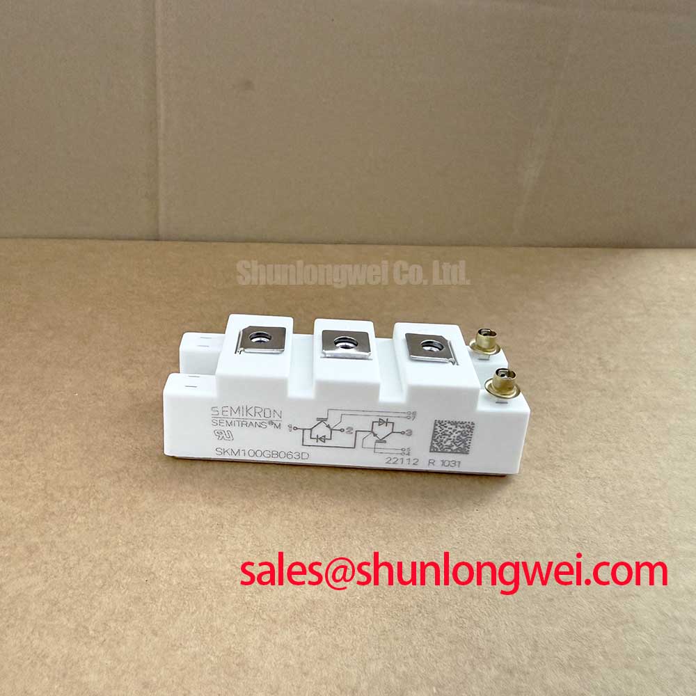
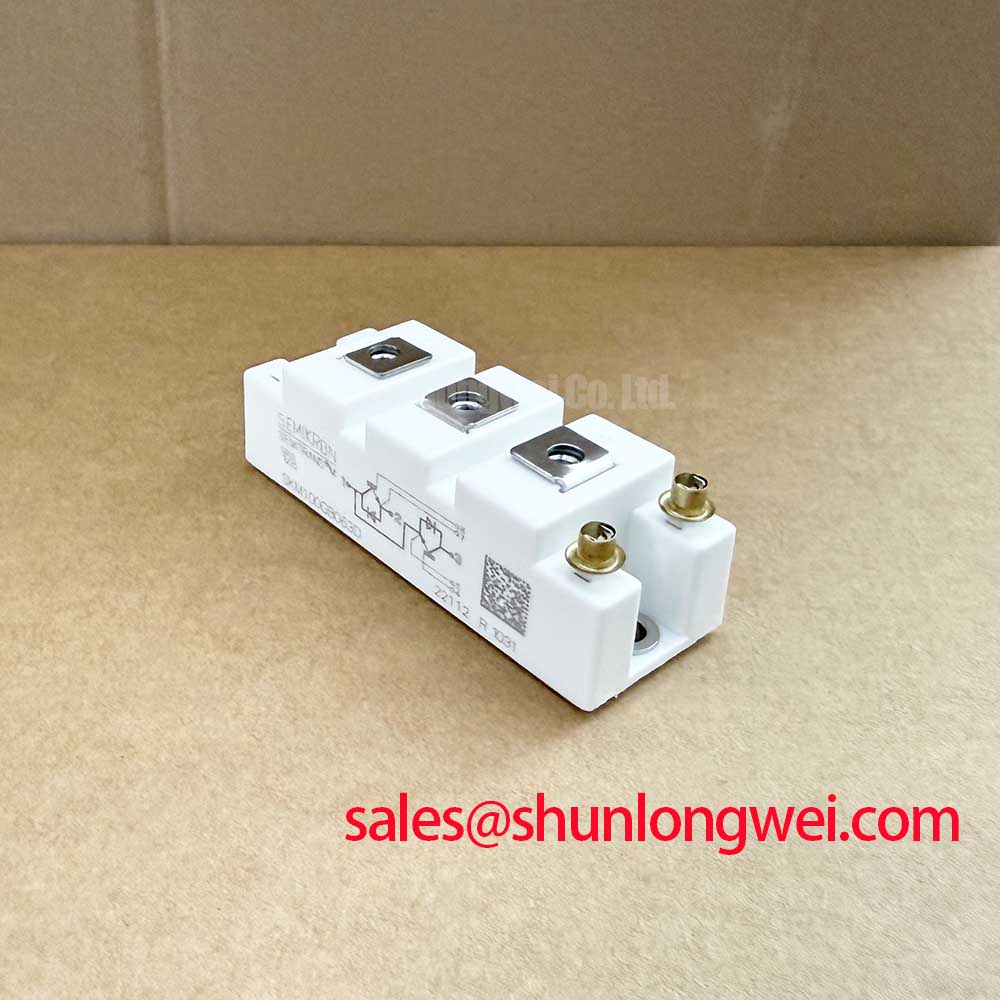
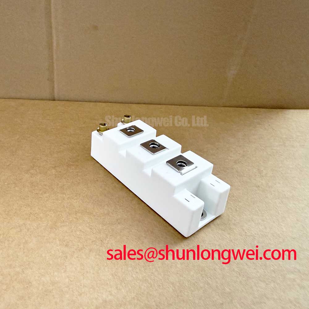
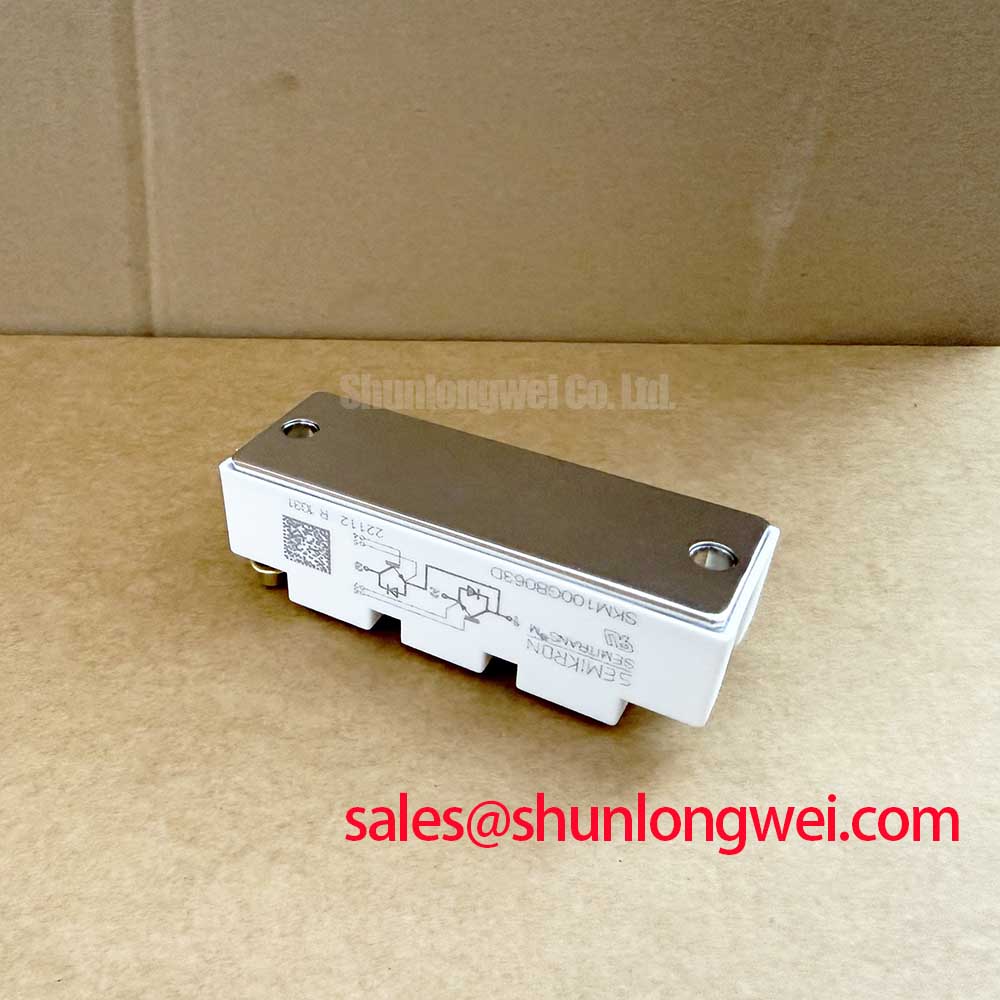
In high-cycling battery energy storage system (BESS) power conversion systems (PCS), thermal interface degradation remains one of the primary drivers of localized semiconductor over-temperature failures. The Semikron SKM100GB063D utilizes an industry-standard copper baseplate structure designed to transfer heat across a rated junction-to-case thermal resistance of Rth(j-c) = 0.18 °C/W per IGBT switch (Official Datasheet Specification). Maintaining this heat path requires strict control of the thermal interface material (TIM) layer thickness, void elimination, and a calibrated fastener tightening sequence during field replacement or regular preventive overhaul.
During installation onto an extruded or cold-plate heatsink, baseplate pre-bowing (convexity engineered into the module) must be flattened uniformly against the mating surface. If the thermal paste is applied too thick (exceeding 100 μm), the paste itself acts as a thermal barrier, artificially increasing the case-to-sink thermal resistance Rth(c-s). Conversely, applying an insufficient layer (below 40 μm) fails to fill microscopic machining grooves and surface voids, leading to localized dry spots and premature junction thermal fatigue under rapid PCS charge-to-discharge load transitions.
For consistent thermal performance, technicians should apply a non-curing, high-thermal-conductivity silicone or synthetic grease using a precision screen printer or a notched rubber squeegee to achieve a uniform wet film thickness between 50 μm and 80 μm. Evaluating interface durability under extreme cyclical thermal stress aligns with standards established in Thermal Shock Testing (MIL-STD-202) for Power Modules, validating mechanical integrity across repeated heating and cooling sequences.
Fastener torque calibration must follow a multi-step cross-pattern to prevent warping the internal direct bonded copper (DBC) substrate:
- Heatsink M5 Mounting Screws: Pre-tighten diagonally to an initial seating torque of 0.5 to 1.0 N·m. Allow grease relaxation for 15 to 30 minutes, then apply final torque within 3.0 to 5.0 N·m (Official Datasheet Specification).
- Main Power Terminals (M5): Fasten DC busbars and AC output connections strictly between 2.5 and 5.0 N·m (Official Datasheet Specification). Over-torquing risks shearing the internal terminal nut or cracking the surrounding housing resin.
- Heatsink Surface Preparation: Surface flatness across the mounting footprint must remain within ≤ 50 μm per 100 mm, with a surface roughness Rz ≤ 6.3 μm to avoid pinching the module baseplate.
⚠️ Maintenance Note: During semi-annual PCS maintenance, conduct an infrared thermographic scan while running the inverter at full rated current (IC = 100 A). A temperature differential (ΔT) exceeding 12 °C between two adjacent parallel modules or an unexpected case-to-heatsink temperature rise indicates grease pump-out, dry-out, or terminal torque relaxation, requiring immediate module unmounting, cleaning with isopropyl alcohol, and re-greasing.
High-Altitude Cosmic Ray Induced SEB Failure & FIT Rate Mitigation
Commercial and industrial energy storage systems deployed in mountainous or high-altitude terrain (elevations exceeding 2,000 meters above sea level) face an increased flux of atmospheric cosmic ray neutrons. When a high-energy terrestrial neutron strikes the high-electric-field space-charge region of a reverse-biased IGBT or free-wheeling diode, it generates a localized electron-hole plasma filament. This localized carrier concentration can trigger Single Event Burnout (SEB), causing catastrophic, instantaneous collector-to-emitter breakdown without any prior thermal warning.
The SKM100GB063D is rated for a maximum collector-emitter blocking voltage of VCES = 600 V at Tj = 25 °C (Official Datasheet Specification). Because cosmic-ray-induced Failures in Time (FIT rate, defined as failures per 109 component operating hours) scale exponentially with applied DC-link voltage, plant operators must establish a derating profile based on installation altitude:
| Installation Altitude | Atmospheric Pressure (Ref) | Recommended Maximum Continuous DC Bus Voltage | Engineering Assessment |
|---|---|---|---|
| Sea Level to 1,000 m | ~101.3 kPa | 400 V DC to 420 V DC | Standard operating envelope; baseline neutron FIT rate. |
| 1,000 m to 2,000 m | ~79.5 kPa | 360 V DC to 380 V DC | Moderate derating (Design Consideration) to keep FIT rate within industrial limits. |
| 2,000 m to 3,500 m | ~65.8 kPa | 300 V DC to 330 V DC | Aggressive voltage ceiling required; secondary clearance and creepage checks mandatory. |
For PCS architectures requiring higher continuous DC bus levels (such as 600 V to 800 V battery strings), using a 600 V silicon switch provides insufficient cosmic ray and inductive turn-off voltage headroom. In those topologies, engineers evaluate higher-voltage modules such as the SKM100GB124D, which provides a blocking rating of VCES = 1200 V to handle wider DC margins.
When investigating unexpected field trips or insulation degradation at high-altitude installations, technicians can consult practical diagnostic sequences outlined in the Field Engineer’s Handbook to distinguish between atmospheric SEB events and routine switching overvoltage punch-through.
Common-Mode Transient Immunity (CMTI > 100kV/us) in Harsh Industrial Environments
Battery energy storage converters generate rapid voltage transitions (high dv/dt) across the half-bridge phase legs during high-frequency pulse-width modulation (PWM). In noisy industrial environments, rapid potential shifts on the switching node couple high-frequency displacement currents across the galvanic isolation barrier of the gate driver stage. If the isolation barrier lacks sufficient Common-Mode Transient Immunity (CMTI), these displacement currents corrupt gate control signals, creating missing pulses or generating spurious gate turn-on triggers.
To ensure system stability, driver boards interfacing with the SKM100GB063D require galvanic isolation channels rated for CMTI exceeding 100 kV/μs. The internal half-bridge layout contains two IGBT switches with integrated anti-parallel CAL (Controlled Axial Lifetime) diodes, specified with a typical forward voltage drop of VF = 2.0 V at IF = 100 A (Official Datasheet Specification). Fast recovery of this diode under steep reverse di/dt induces sharp common-mode voltage steps that travel back toward the digital control processor.
Key board-level layout considerations for preserving gate signal integrity include:
- Parasitic Capacitance Minimization: Maintain primary-to-secondary coupling capacitance below 1.5 pF across isolated DC-DC auxiliary power supply transformers.
- Shielded Gate Drive Traces: Run gate and auxiliary emitter connections as tight differential twisted pairs or closely coupled inner PCB striplines, minimizing the parasitic loop area directly connected to terminals 4 and 5 (lower switch) and terminals 6 and 7 (upper switch).
- Galvanic Isolation Standards: Use digital isolators or high-speed optocouplers compliant with reinforced insulation standards (VISO ≥ 4000 V AC for 1 minute) to isolate control logic from noisy power ground planes.
High dv/dt Cross-Conduction Shoot-Through Mitigation via Dedicated Miller Clamps
In a half-bridge topology, when the active IGBT turns on, the complementary off-state IGBT experiences a rapid rise in collector-emitter voltage (dv/dt). This voltage swing drives a displacement current through the internal reverse transfer capacitance (Miller capacitance, Cres) into the off-state gate circuit. If the gate driver relies solely on a high pull-down impedance or a unipolar 0 V off-state rail, this displacement current creates a voltage drop across the turn-off gate resistor, elevating the gate voltage above the threshold level (VGE(th)) and causing phase-leg cross-conduction (shoot-through).
The SKM100GB063D exhibits a forward saturation voltage of VCE(sat) = 2.1 V typical (2.5 V maximum) under IC = 100 A and VGE = 15 V (Official Datasheet Specification). Maintaining this low conduction loss profile while safeguarding against shoot-through requires active gate-circuit management during switching transitions:
- Dedicated Active Miller Clamp: Implement a low-impedance internal or external clamp transistor that continuously monitors gate voltage. When VGE falls below ~2.0 V during turn-off, the clamp activates, tying the gate directly to the negative auxiliary rail or ground via a dedicated low-impedance path (< 1.0 Ω).
- Negative Gate Turn-Off Bias: Drive the off-state gate with a true bipolar supply voltage (such as +15 V / -8 V to -15 V Design Consideration). The negative voltage margin absorbs Miller charge displacement without allowing the gate potential to rise toward the threshold region.
- Gate Damping Resistance Tuning: Select an initial turn-on/turn-off external gate resistance (such as 10 Ω to 22 Ω Typical Starting Point) to balance collector current rise time against peak turn-off overvoltage spikes caused by stray bus inductance.
Field troubleshooting of suspected shoot-through begins by capturing the gate-to-emitter waveform with a high-bandwidth differential probe directly at the module terminals during full-load PCS operation. If a positive voltage spike on the off-state gate exceeds 1.5 V during the opposite switch's turn-on transient, the active Miller clamp circuit or negative bias supply must be inspected and tuned to prevent thermal stress and degradation on the module DBC substrate.