

Content last revised on October 4, 2026
SKM200GAL125D Circuit Protection & Reliability: Calibrating High-Frequency Commutation Loop Inductance
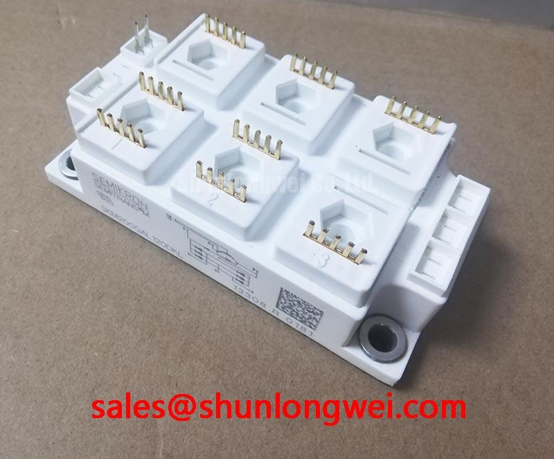
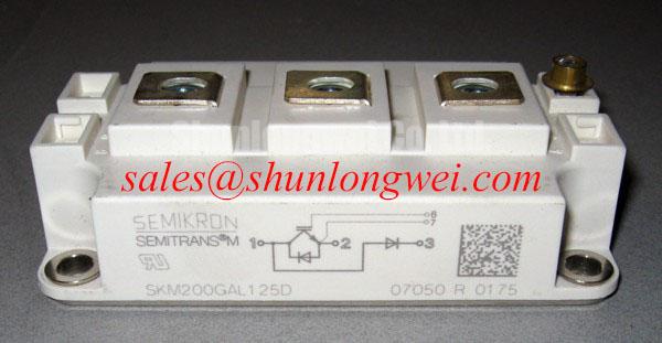
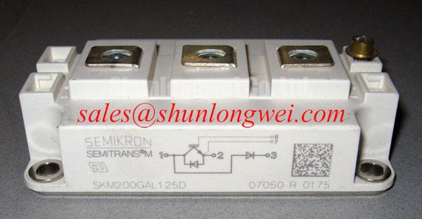
SKM200GAL125D is a Semikron IGBT module in a Semitrans package, rated at 1200 V and 200 A (Official Datasheet Specifications).
Probe the collector-to-emitter voltage at turn-off and compare its peak with the measured DC-link voltage when investigating a failed switching stage. The difference can reveal inductive overshoot, although probe placement and bandwidth can distort a fast transient. For SKM200GAL125D, the 1200 V rating is an Official Datasheet Specification, not an allowable repetitive overshoot target. Capture the waveform under representative operating conditions and assess the peak against the module rating and the equipment’s protection strategy.
As an Engineering Calculation, the voltage across commutation-loop inductance rises with inductance multiplied by the rate of current change. That relationship explains why a layout that appears acceptable at light load can produce a markedly different turn-off waveform at higher current. Trace the physical loop through the module terminals, DC-link capacitors, busbar and return path rather than judging it from the circuit diagram alone. Keep opposing current paths close and the busbar geometry balanced; the system designer must establish the required spacing and verify the resulting voltage margin during switching tests. These are Design Considerations, not specified inductance or clearance limits for this module.
Where a snubber is present, inspect its connection to the switching terminals and compare measured waveforms with a known-good stage. Its capacitance and damping depend on the actual loop, switching behavior and dissipation; selecting them from the module’s current rating alone is unreliable. A clamp should be assessed against the voltage seen at the module terminals, including wiring between the clamp and the device. 💡 Pro Tip: Keep the busbar return path symmetrical to reduce turn-off overshoot, then verify the voltage margin with a double-pulse measurement before accepting the layout.
When a commercial string inverter or micro-grid energy storage converter is being repaired, treat its busbar, capacitor bank and protection circuit as part of the compatibility check. A module with the correct headline ratings does not establish that the assembled converter has adequate switching margin. The broader drive-oriented discussion in Unlocking Efficiency in Industrial Drives offers context for switching-loss and margin assessments; its technology-specific observations should not be assumed to describe SKM200GAL125D.
SKM200GAL125D Operational Boundaries: Evaluating Dynamic Gate Impedance Control for Robust Limits
Measure the gate-to-emitter waveform of the device that should remain off while the adjacent switch commutates. An unexpected gate excursion may point to capacitive coupling through the collector-to-gate path, a shared return impedance, or driver behavior; it does not by itself identify a defective module. Compare the waveform at the driver output and at the module gate connection, using the same measurement method on a working stage if one is available.
Gate impedance affects switching speed and the time spent around the Miller plateau. In a Design Consideration, faster voltage transitions can increase current coupled into an off-state gate, while excessive turn-off impedance can reduce control over that excursion. An active Miller clamp is one possible driver-circuit measure, but its operation depends on the actual driver, gate return and device connections. Inspect the existing schematic and measure the off-state waveform before changing the gate network. Any gate-bias adjustment must remain within the applicable device and driver limits; no bias setting follows from the 1200 V and 200 A ratings alone.
Check the current and voltage waveforms around diode commutation as well. Reverse recovery can change the current slope and contribute to ringing when combined with loop inductance. Recovery softness is useful as an engineering concept, but no softness factor or reverse-recovery value is established by the specifications stated here. If a snubber change reduces ringing, confirm its effect across the equipment’s operating range and check its thermal burden. Radiated-emissions performance belongs to the assembled converter and its measured installation configuration, not to the IGBT module in isolation.
A bootstrap-fed high-side driver warrants a separate check when its gate waveform weakens during repeated switching. Observe the driver supply at the relevant switching conditions, then examine capacitor recharge opportunities and the bootstrap diode’s behavior in the installed circuit. Driver supply margin, diode recovery and gate-charge demand must be assessed together from the equipment design; the module’s headline voltage and current ratings cannot determine a bootstrap capacitor value.
Transient Dynamics & Electrical Design: Symmetrical Busbar Geometry for High-Current Operation on SKM200GAL125D
Compare current waveforms in parallel switching paths before attributing unequal loading to the modules. Differences in busbar length, DC-link connections, gate routing or cooling can produce unequal behavior even where the fitted parts carry the same model number. The 200 A rating is an Official Datasheet Specification for SKM200GAL125D; it should not be multiplied by the number of parallel positions to infer a safe assembly current without evaluating thermal and dynamic sharing.
For static sharing, examine each installed device’s conduction behavior at its operating temperature rather than assuming that a positive temperature coefficient guarantees balance under all conditions. Dynamic sharing needs a separate measurement: compare gate-to-emitter and collector-to-emitter waveforms during turn-on and turn-off, and inspect whether each device sees similar power and gate-loop impedance. Symmetrical busbar geometry and matched gate-routing conditions are Design Considerations intended to limit avoidable imbalance; acceptance depends on measured behavior in the completed assembly.
Include the mechanical interface in that comparison. Uneven contact between a module base and heatsink can alter thermal behavior without an obvious electrical fault at room temperature. Inspect mounting surfaces, follow the equipment’s interface-material procedure and obtain the applicable mounting instructions for the installed hardware rather than transferring a generic grease thickness or bolt torque to this Semitrans package. Semikron-Danfoss describes the SEMITRANS family of industrial power modules; family information provides package context but does not replace the mounting requirements for the exact assembly.
During a repair evaluation, compare the original circuit position, terminal arrangement, ratings, cooling interface and gate drive before considering another part. SKM75GAL063D can be examined as a separate Semikron module candidate in a sourcing review, but its model designation is not evidence of electrical or mechanical interchangeability with SKM200GAL125D. The equipment-level comparison must resolve that question.
Transient Dynamics & Electrical Design: PCB Gate Loop Layout Symmetry on SKM200GAL125D
Trace the gate-drive return from the driver to the module connection when gate ringing persists after the power loop has been checked. If gate-return current shares a conductor with high-current emitter current, the resulting voltage drop can disturb the effective gate-to-emitter voltage. Separate the sensitive drive return from the main power-current path where the verified terminal arrangement permits it, and compare waveforms measured at the module with those measured at the driver.
Do not assume an auxiliary Kelvin emitter terminal is present from the module name or package family. Establish the exact terminal functions from the connection drawing and the installed assembly before routing a dedicated return. Where the available connections do not provide an independent return, concentrate on a compact gate loop, controlled shared impedance and measured gate behavior. These are Design Considerations to be resolved in the actual PCB and module interface, not claims about an undocumented internal structure.
Inspect the gate resistor, driver return, connector contacts and nearby power traces if oscillation appears only at particular load currents. A changed waveform may have more than one contributor: busbar ringing can couple into the gate path, while driver supply movement can resemble a gate-network problem. Preserve the same probing reference and operating conditions when comparing phases. For a converter topology review, SKM100GB063D is another module that may appear in a related power-stage assessment; confirm its assigned circuit role from the equipment schematic rather than treating it as a specified rectifier or companion to SKM200GAL125D.
If the equipment is intended for an installation with unusual environmental demands, review its specified operating limits and protection requirements at system level. Altitude, insulation coordination and reliability margins cannot be inferred from the package name. Complete the gate-loop assessment with waveforms at the module terminals, heatsink-contact inspection and the equipment’s documented acceptance criteria.