

Content last revised on October 2, 2026
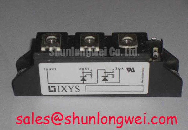
Transient Dynamics and Thermal Interface Care for MID200-12A4
Before mounting the replacement, clean the heatsink contact surface and inspect it for raised edges, debris and old thermal compound. Apply thermal interface material evenly, following the material supplier’s instructions and the equipment’s mounting procedure. Excess compound and trapped voids can both obstruct consistent contact. If the baseplate or heatsink appears distorted, check flatness against the applicable assembly documentation rather than trying to correct poor contact by tightening one fastener harder.
As a Design Consideration, bring mounting screws into contact progressively and tighten them in a balanced sequence to limit uneven pressure. Use the specified fasteners and torque from the original assembly documentation; the supplied MID200-12A4 specifications do not establish a mounting torque. Check electrical clearances against the equipment drawing after routing the busbars, since the 1200 V rating does not itself define a safe spacing for a particular installation.
During planned maintenance, compare heatsink cleanliness, airflow and measured contact temperatures with the equipment’s established baseline. ⚠️ Maintenance Note: Isolate the equipment before disturbing module terminals, and investigate a rising contact temperature alongside airflow and thermal interface condition.
MID200-12A4 Boundaries in Bidirectional DC Conversion
For a commercial string inverter or micro-grid storage system, the 1200 V and 200 A Official Specifications are useful screening values when evaluating a DC conversion stage. They do not, on their own, establish suitability for battery charge and discharge cycles. Designers should verify the actual circuit topology, current waveform, switching conditions and thermal limits against the original device documentation and the equipment design.
As a Design Consideration, keep the switching current loop compact to reduce turn-off overshoot caused by busbar parasitic inductance. Place any system-required snubber film capacitor according to the power-stage layout and validate its effect with switching measurements. The acceptable inductance, capacitor arrangement and voltage margin are system-determined; none can be inferred from the module’s voltage and current ratings alone.
On equipment that repeatedly moves between charging and discharging, log case or heatsink temperature through representative operating cycles rather than relying on a steady-load reading. If measured peaks drift upward, check cooling flow, terminal contact and the switching waveform before attributing the change to the module. A related component such as MBM200H45E2-H may appear in a wider power-stage assessment, but its circuit role and compatibility require independent verification.
Assembly Integrity and Pulsed Thermal Response
A pulsed overload can raise junction temperature faster than the heatsink temperature indicates. Evaluating that response requires the device’s junction-to-case transient thermal data, the measured loss profile and the installed cooling path. The supplied ratings do not include a transient thermal impedance curve, so a numerical peak junction-temperature margin would be unsupported. For a repair decision, obtain the applicable IXYS documentation and compare the recorded duty cycle with its thermal limits before returning the equipment to sustained service.
Inspect busbar contact faces and terminal hardware while the assembly is open. Uneven contact, loose connections and restricted airflow can each affect observed temperatures; a hot location alone does not identify which one is responsible. ROHM’s IGBT technical material provides general context for IGBT switching and thermal behaviour, but does not establish the internal construction or thermal constants of MID200-12A4.
MID200-12A4 Boundaries in Parallel Current Sharing
When a power stage uses parallel modules, do not assume that matching 1200 V and 200 A nameplate ratings guarantees equal current sharing. Compare the original schematic, terminal arrangement, gate-drive paths and cooling layout before evaluating a replacement. A positive temperature coefficient can aid static sharing in some IGBT operating regions, but its applicability to MID200-12A4 must be established from device-specific characteristics rather than presumed.
As a Design Consideration, route parallel power and gate connections symmetrically to limit differences in switching timing and current paths. Verify dynamic balance with suitable current and voltage measurements under controlled operating conditions. Gate-loop oscillation or turn-off overshoot warrants checking connection integrity and parasitic coupling against a known-good stage; it is not a diagnosis by itself. The IGBT knowledge base and an overview of trench-gate technology offer general background, not a substitute for this model’s specifications.
If the repair bill of materials lists MBM200JS12EW as an alternative to investigate, compare its documented topology, terminals, mounting pattern, drive requirements and thermal behaviour with the original equipment requirements before approving a substitution.