Content last revised on September 10, 2026
Engineering Overview: Fuji Electric 1MBI200S-120 in Industrial Power Conversion
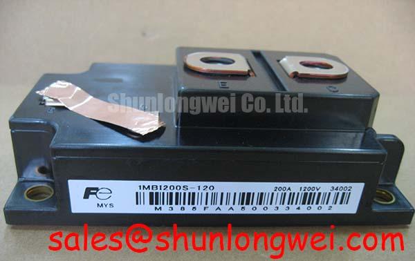
In high-stress industrial environments such as medium-frequency induction heating power supplies and heavy-duty industrial inverter welders, switching devices face harsh electrical transients, rapid thermal cycling, and aggressive factory atmospheres. The 1MBI200S-120 single IGBT module from Fuji Electric Power Semiconductor & IPM Modules is designed to handle demanding industrial power topologies requiring high current handling and reliable thermal dissipation.
For plant maintenance engineers, reliability specialists, and equipment overhaul teams, maintaining uptime requires a granular understanding of baseline electrical limits, mechanical mounting practices, gate-drive layout symmetry, and fault protection timing. The table below presents the verified factory parameters essential for bench testing, thermal budgeting, and preventative replacement planning.
| Parameter | Datasheet Rating | Classification | Operational Significance |
|---|---|---|---|
| Collector-Emitter Voltage (VCES) | 1200 V | Official Specification | Provides dielectric withstand and turn-off margin for rectified 380V–480V three-phase lines. |
| Continuous Collector Current (IC) | 200 A (@ TC = 80°C) | Official Specification | Permits high power throughput in compact induction workheads and welding bridges. |
| Collector-Emitter Saturation Voltage (VCE(sat)) | Typ. 2.3 V (IC = 200 A, VGE = 15 V) | Official Specification | Minimizes direct conduction loss during high-duty welding cycles. |
| Thermal Resistance Junction-to-Case (Rth(j-c)) | 0.085 °C/W (IGBT section) | Official Specification | Determines steady-state and transient heat transfer from silicon die to copper baseplate. |
| Isolation Voltage (Visol) | 2500 V AC (1 minute) | Official Specification | Ensures primary-to-chassis dielectric isolation meeting industrial plant safety codes. |
Baseplate Convexity Compensation and Screw Tightening Sequence Guidelines
The copper baseplate of high-power modules like the 1MBI200S-120 features an engineered pre-bow (convexity) to ensure that when bolted down, interfacial pressure forces the center of the module into intimate contact with the heatsink. Improper mounting technique creates air pockets, excessive thermal interface material (TIM) build-up, and localized thermal hotspots that accelerate die-attach fatigue.
Achieving a reliable thermal path begins with heatsink surface preparation. The mounting surface flatness must remain within 50 µm across the entire module footprint, with a surface roughness of Rz ≤ 10 µm. Before mounting, clean the mating surfaces thoroughly using isopropyl alcohol to eliminate metal shavings, industrial particulates, and dried silicone remnants from legacy hardware.
Apply a high-performance, non-curing thermal grease using a calibrated metal or rubber squeegee through a stainless-steel screen stencil. The target wet grease thickness should be maintained strictly between 50 µm and 100 µm (General Industry Design Consideration for standard industrial baseplates). Applying too little grease leaves insulating microscopic voids, while excessive grease increases overall thermal impedance because TIM thermal conductivity is far lower than copper or aluminum.
⚠️ Maintenance Note: In medium-frequency induction heaters subjected to continuous load cycling, thermal grease undergoes microscopic displacement known as "pump-out." Inspect heatsink-to-baseplate thermal margins during scheduled plant overhauls every 12 to 18 months. Re-paste the thermal interface whenever thermal imaging reveals a junction-to-heatsink delta exceeding baseline commissioning profiles by more than 15°C under equivalent load currents.
To ensure uniform baseplate flattening and avoid cracking internal ceramic substrates (Al2O3/AlN DBC), use a calibrated torque wrench and follow a two-step fastening sequence for the standard M5 mounting screws:
- Step 1 (Pre-tightening): Tighten screws in diagonal order to an initial seating torque of 0.5 N·m to 1.0 N·m (Design Consideration). This seats the module evenly across the grease layer without binding.
- Step 2 (Final Torque): Incrementally torque each screw to the final target of 2.5 N·m to 3.5 N·m (Standard Industry Design Consideration for M5 threads in extruded aluminum heatsinks). Allow the thermal paste to settle for 20 to 30 minutes, then perform a final torque verification check.
- Main Terminal Fastening: When securing DC busbars and AC output links to the M5 electrical terminals, limit torque to 2.5 N·m to 3.5 N·m. Excessive mechanical strain on terminal studs causes internal lead-frame stress and microscopic cracking of the housing potting gel.
PCB Symmetry Considerations for Dual IGBT Half-Bridge Switching Paths
Industrial inverter welders rely on rapid switching to maintain precise weld-pool arc stability. At switching frequencies between 20 kHz and 50 kHz, parasitic loop inductance within the power stage and gate-drive circuitry becomes a primary source of electromagnetic interference (EMI), gate oscillations, and localized overvoltage transients.
A frequent error encountered during cabinet retrofits is the improper routing of the auxiliary Kelvin emitter connection. The high-current main emitter carries massive pulse currents with steep rates of change. If the gate driver return path shares trace area with the power emitter terminal, the induced voltage drop across the shared parasitic inductance subtracts directly from the applied gate-to-emitter drive voltage during turn-on and adds to it during turn-off, inducing destructive gate ringing or spurious turn-on through the Miller capacitance.
To ensure clean gate transitions, route the gate and Kelvin emitter connections as tightly coupled twisted-pair wiring or parallel PCB traces routed on adjacent inner layers. Maintain an initial gate damping resistance around 10 Ω (Typical Starting Point for bench tuning), fine-tuning upward if turn-off ringing exceeds 10% of nominal drive rails, or downward if turn-on switching losses dominate the thermal budget.
When working on plant modernization programs where legacy sub-assemblies operate on lower DC bus levels, engineering teams evaluating alternative voltage classes for lower-voltage industrial drives may review the 1MBI200NH-060 as a reference for 600V-class module packaging and circuit footprints.
Mitigate bus overvoltage spikes by deploying laminated DC busbars combined with low-inductance polypropylene film snubber capacitors installed directly across the module collector-emitter power terminals. In induction heating topologies, phase-angle conduction shifts and line-frequency harmonic currents generate secondary voltage spikes; an optimized RC snubber network suppresses high-frequency ringing and protects the IGBT from exceeding its official rated VCES of 1200V.
Fault-Clearing Dynamics: Type-I/II Desaturation Detection and Inductive Clamping
In induction heating tanks and high-current welding torches, external short circuits are recurring operational hazards. These faults divide into Type-I (hard turn-on into an existing shorted coil or grounded cable) and Type-II (flashover or insulation breakdown while the IGBT is already in full saturation mode).
The short-circuit safe operating area (SCSOA) dictates that the 1MBI200S-120 can withstand a full dead short for a maximum duration of 10 µs under specified test conditions (Official Datasheet Specification: tsc ≤ 10 µs at VCC = 800V, VGE = 15V, Tj = 125°C). The gate driver protection circuitry must detect the desaturation condition, evaluate the fault, and complete current interruption well inside this 10 µs boundary.
A reliable desaturation detection circuit monitors the collector-emitter voltage via a high-voltage blocking diode. During turn-on, a blanking filter (typically set between 1.5 µs and 2.5 µs) prevents false tripping caused by the initial tail of the collector-emitter falling voltage. Once the blanking time elapses, if VCE exceeds the preset threshold (typically 6.5 V to 8.0 V, Design Consideration), the driver initiates an active soft turn-off (2-Stage Soft Turn-Off, or 2SSTO).
Attempting to snap the gate shut abruptly under a 200 A to 800 A fault current induces extreme voltage spikes across the stray loop inductance, easily destroying the silicon through collector-emitter breakdown. A two-stage turn-off reduces the gate voltage to an intermediate level (e.g., 8 V to 10 V) for 2 µs to 4 µs before pulling down to the negative bias rail (-5 V to -10 V). This controlled ramp lowers the rate of current decay, clamping peak overvoltage within safe limits.
For rigorous bench verification routines, diagnostic procedures, and oscillographic gate-wave analysis of failed modules, maintenance leads can consult the comprehensive diagnostic protocols in the Field Engineer’s Handbook.
Static and Dynamic Current Distribution across Paralleled IGBT Switches
High-capacity medium-frequency induction heaters (100 kW to 300 kW) frequently require paralleling two or more 1MBI200S-120 modules to scale current capability. Balancing current among parallel branches requires attention to both steady-state (static) and switching transient (dynamic) operating domains.
Static current sharing relies on the positive temperature coefficient of the saturation voltage at higher operating currents. The 1MBI200S-120 features a typical VCE(sat) of 2.3 V at 200 A. At elevated junction temperatures, VCE(sat) increases slightly, naturally shifting excess current toward the cooler module and preventing steady-state thermal runaway across the array.
Dynamic current sharing, however, depends entirely on symmetry in physical layout and gate drive timing. The following design rules must be applied during cabinet layout or major inverter rebuilds:
- Individual Gate Resistors: Never drive paralleled modules through a single shared gate resistor. Provide dedicated series gate resistors and pull-down networks for each module to prevent high-frequency circulating currents between adjacent gate terminals.
- Symmetrical Busbar Geometry: Match the physical lengths, cross-sectional areas, and parasitic inductances of the DC+ and DC- input feeds. An asymmetry of just 5 nH between branches causes unequal current sharing during the initial 200 ns of the switching transition.
- Thermal Coupling: Mount paralleled modules on a common high-conductivity heatsink block in close physical proximity. This ensures that ambient variations or localized liquid coolant flows do not induce wide thermal gradients across matched pairs.
- Gate Drive Signal Skew: Ensure driver output traces to both modules have matched propagation delays (skew ≤ 10 ns) to guarantee simultaneous turn-on and turn-off transitions.
Adhering to these mechanical, electrical, and thermal guidelines ensures predictable power stage performance, protects power electronics assets against unexpected downtime, and extends module operational life across challenging manufacturing processes.