Content last revised on October 1, 2026
CM150DX-24A and Long Motor Cable Voltage Reflections
Measure the voltage waveform at the motor terminals and compare it with the inverter output waveform when unexplained overvoltage alarms occur on a long cable run. Reflections caused by a mismatch between cable and motor impedance can raise motor-terminal peaks above the inverter output step. The result depends on cable length, rise time, termination, and the complete drive circuit; it cannot be inferred from the module rating alone.
For a heavy-duty variable frequency AC motor drive under evaluation, distinguish a motor-terminal reflection from a voltage spike at the IGBT terminals. The 1200 V rating is the CM150DX-24A collector-to-emitter voltage boundary (Official Specification), not an allowable motor-terminal peak. Use appropriately rated differential probes and capture both locations under representative switching conditions. If the motor-end waveform points to reflections, assess an output filter or choke against the drive, cable, and motor requirements rather than sizing it from the IGBT rating.
As a Design Consideration, route output conductors and protective earth consistently, then check cable clearances and insulation coordination against the equipment design. Keep measurement leads short enough to avoid mistaking probe-loop pickup for ringing. If alarms persist after an output-network change, compare the gate command, phase-current waveform, and DC-link behavior with a known-good operating condition before assigning the fault to the module.
CM150DX-24A Pulsed Loading and Junction Temperature Margin
Capture phase current and case temperature during the overload event, then establish whether the protection trip follows a current pulse or a slower rise in heatsink temperature. The 150 A current rating (Official Specification) is a device rating, not a blanket approval for every pulse duration, switching frequency, or cooling arrangement. A repair assessment must account for the installed heatsink, switching losses, and the equipment’s overload sequence.
Transient thermal impedance describes how junction temperature responds before heat flow reaches steady state. As an Engineering Calculation, junction-temperature rise for a specified pulse is estimated from the device’s loss waveform and its applicable transient thermal impedance curve; successive pulses require their thermal contributions to be accumulated. Without the CM150DX-24A thermal curves and loss conditions, a numerical peak-junction-temperature margin would be speculative. The system engineer should evaluate the original module documentation and confirm the result against measured case temperature under representative duty.
Inspect the heatsink contact surface when the calculated and measured behavior disagree. Uneven clamping, contamination, or gaps in thermal interface material can increase the temperature drop between the module and heatsink. As a Design Consideration, apply the specified interface material uniformly, seat the module without rocking, and follow the mounting sequence and torque stated for the actual assembly. Do not treat a generic screw torque or paste thickness as a Mitsubishi Electric specification for this part.
For broader context on duty cycles and application-level checks, see Industrial Applications. That discussion does not replace a device-specific thermal calculation or validation on the installed drive.
CM150DX-24A DC-Link Layout and Switching Overshoot
Probe the DC link at the module connection and capture collector-to-emitter voltage at turn-off if failures coincide with fast current changes. Busbar and capacitor-bank stray inductance can add an overshoot to the DC-link voltage; the measured peak, rather than the nominal bus voltage, must be assessed against the 1200 V collector-to-emitter rating (Official Specification). Probe placement matters because a distant capacitor terminal may conceal the voltage seen at the module.
As a Design Consideration, keep the commutation path compact and arrange opposing current paths to limit loop inductance. Check that DC-link capacitors, busbar joints, and any snubber are connected as intended before changing gate-drive settings. A snubber choice depends on measured ringing, energy, and component stress; the module’s voltage and current ratings alone do not establish its capacitance. Pro Tip: Compare turn-off waveforms across representative load conditions before accepting a busbar or snubber change.
Gate-drive layout deserves a separate check. Trace the gate and emitter-return conductors against the original schematic, keeping the control loop away from high-current paths where the hardware permits. Do not assume a dedicated auxiliary or Kelvin emitter terminal exists without confirming the CM150DX-24A terminal drawing. If the opposite switch shows unintended gate movement, inspect the driver return, Miller-current path, and isolation behavior during switching. An optocoupler or digital isolator must be evaluated for the common-mode transients produced by the complete drive, not selected solely from the IGBT nameplate.
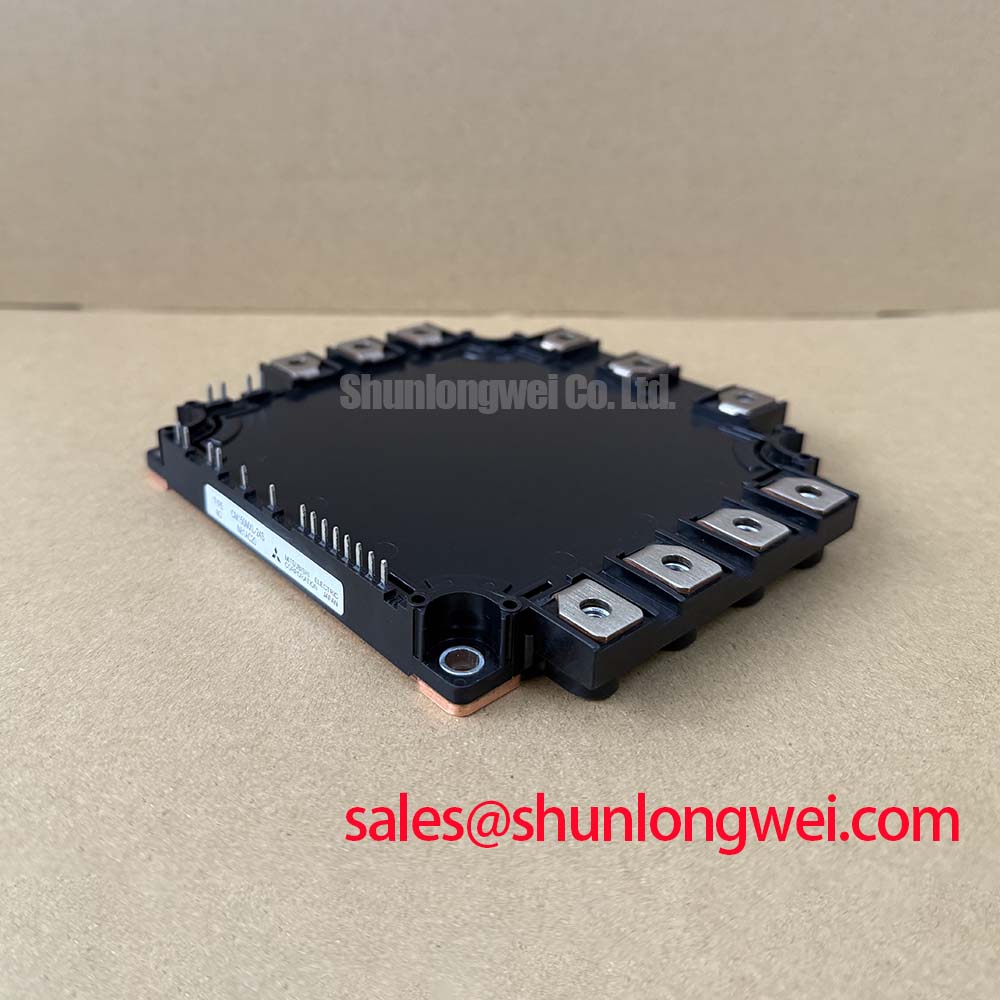
For replacement screening, CM150MXUD-24T is a separate model to compare at the drawing and datasheet level. Check terminal arrangement, mounting interface, thermal behavior, switching characteristics, and driver compatibility before treating it as interchangeable. Mitsubishi Electric’s NX-Series IGBT Modules information provides context for another module family; family-level information does not establish CM150DX-24A specifications.
CM150DX-24A Heatsink Contact and Protection Checks
Check the module-to-heatsink contact pattern and the protection log when a repaired drive trips only after warming up. Look for local gaps in the thermal interface, a damaged mounting surface, or fasteners that have not seated evenly. Clean and inspect mating surfaces before reassembly, and use the equipment’s approved mounting instructions for interface application and sequential tightening. A visually continuous interface is useful evidence, but temperature measurements under load are needed to judge its performance.
Review desaturation or overcurrent events alongside gate-drive supply and phase-current records. A thermal trip, a short-circuit response, and a switching overshoot call for different measurements; none can be established from a single alarm label. During commissioning, increase load under controlled conditions and record case temperature, DC-link voltage, and switching waveforms against the equipment’s protection settings. Preserve the drive’s original isolation and clearance scheme when reconnecting the module.
Mitsubishi Electric’s SiC Power Modules and SBDs information describes a different device category and is useful only as technology context, not as a basis for assigning SiC characteristics to this IGBT module. For the CM150DX-24A installation, acceptance rests on the verified terminal arrangement, the stated 1200 V and 150 A ratings, and measurements from the actual drive.