

Content last revised on October 30, 2026
CM150MXL-24S: Pre-Installation Checks and Section Ratings
- Isolate the power assembly, verify DC-link discharge, and record cold-state terminal readings before disconnecting the module.
- Check heatsink contact surfaces, mounting-hole alignment, and terminal loading before loosening the fasteners.
- Compare gate-drive connections and power-terminal identification with the equipment schematic before reconnecting wiring.
- Inspect the driver supply and protection circuit separately so that an upstream fault is not carried into the replacement assembly.
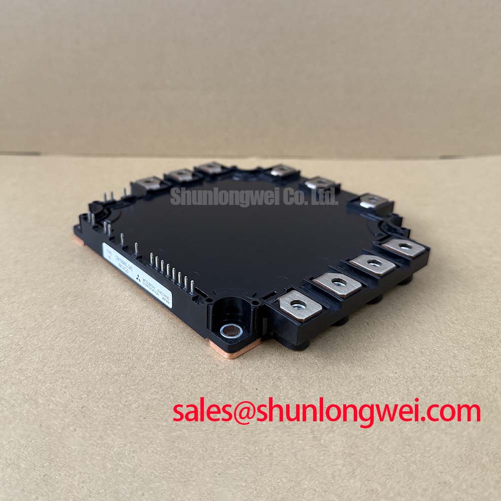
The CM150MXL-24S from Mitsubishi Electric combines inverter/brake and converter section ratings relevant to power-stage assessment. Keep those sections separate when checking voltage limits, conduction losses, and fault protection.
| Section | Parameter | Official Specification |
|---|---|---|
| Inverter/brake | Collector-emitter voltage, Vces | 1200 V |
| Inverter/brake | Collector current, Ic | 150 A |
| Inverter/brake | Typical Vce(sat) at Tj = 125°C | 2.2 V |
| Inverter/brake | Short-circuit withstand time, Tsc | 10 μs |
| Converter | Repetitive peak reverse voltage, Vrrm | 1600 V |
| Converter | Average rectified current, Io | 150 A |
| Converter | Typical forward voltage, Vf | 1.3 V |
| Converter | Surge forward current, Ifsm | 1350 A |
Consult Datasheet for complete test conditions, terminal assignments, dimensions, mounting limits, and surge duration; typical conduction values are not guaranteed maximum values.
Field Diagnostics & Commissioning: Preventing Substrate Damage During CM150MXL-24S Installation
Check the mounting surface for debris, raised edges, and distortion before seating the module. As a Design Consideration, distinguish specified baseplate curvature from damage rather than attempting to flatten the assembly by tightening its mounting screws. Inspect heatsink flatness against the applicable mechanical drawing.
Apply the approved thermal interface material using the assembly process specified for the equipment. Film thickness depends on surface condition, material behavior, and mounting pressure; it should not be treated as a universal module specification. Bring mounting screws down progressively in a diagonal sequence where the mounting pattern permits, using calibrated tooling and the prescribed torque.
Field Alert: Never use mounting screws to pull a misaligned module or unsupported busbar into position. After assembly, verify seating and clearance around the housing before reconnecting the power conductors.
Benchtop Waveform Tuning: Controlling Gate-Emitter Loop Coupling on CM150MXL-24S
Trace the gate-driver return to the emitter connection identified in the terminal drawing, rather than assuming that an auxiliary Kelvin emitter is present. As a Design Consideration, keep the external gate and return paths close together and avoid sharing their return path with high-current conductors wherever the documented terminal arrangement permits.
During controlled switching tests, compare gate-emitter voltage at the module connections with collector-emitter overshoot. Probe placement and common-mode rejection matter: apparent ringing can include measurement artifacts. Select damping and routing changes from measured behavior, while checking the driver isolator’s common-mode transient immunity against the actual switching environment.
Where a bootstrap-powered driver is used, assess recharge opportunities, capacitor voltage droop, and diode recovery within that driver circuit. Mitsubishi DIPIPM™ Bootstrap Circuit Design provides background for its stated product family, not a CM150MXL-24S driver specification. Likewise, CM50MX-24A belongs in a separate topology comparison, not an assumed companion-stage assignment.
Increasing switching frequency changes switching losses and cooling demand. Engineering Recommendation: assess temperature rise with the intended load, enclosure airflow, and ambient conditions, using IGBT Design & Integration as general background rather than a model-specific thermal guarantee.
Assembly Integrity & Layout Architecture: Preventing Terminal Loading on CM150MXL-24S
Check screw engagement and the washer stack before tightening each power terminal. As a Design Consideration, the fastener must develop the intended clamping force without bottoming out, while the connected conductor should sit naturally against the contact surface.
Support busbars and cables independently so their weight and thermal movement do not lever against the module terminals. Preserve electrical clearances specified by the equipment design, including around washers, conductor edges, and adjacent hardware.
For replacement assessment, compare the complete terminal map, circuit configuration, package drawing, and driver requirements. The CM35MXA-24S is a comparison candidate, not an established direct replacement. In forklift traction or electric material-handling equipment, evaluate compatibility with the actual controller architecture rather than inferring suitability from the application name.
Benchtop Waveform Tuning: Coordinating Short-Circuit Energy Let-Through on CM150MXL-24S
Coordinate gate-driver fault shutdown with upstream fault interruption rather than treating the 10 μs short-circuit withstand specification as a fuse-clearing allowance. As a Design Consideration, desaturation detection, blanking, propagation delay, and controlled turn-off must fit the applicable short-circuit test conditions and safe operating limits.
The converter’s 1350 A surge rating does not independently establish a fuse I²t limit. Compare fuse total-clearing data with the applicable semiconductor surge conditions and prospective fault current, accounting for circuit voltage and DC-link stored energy.
During protection validation, capture fault detection, gate shutdown, and collector-emitter overshoot together. Controlled turn-off can reduce overshoot but also changes fault energy. Evaluate any clamp or snubber circuit network against measured transients; protective coordination must be demonstrated at equipment level rather than inferred from either rating alone.