

Content last revised on September 23, 2026
Field Diagnostics and Commissioning for Overvoltage Trip Prevention
During commissioning, begin with the complete switching path rather than testing the IGBT module in isolation. Verify the DC link voltage, gate driver supply, turn on and turn off signals, braking logic, current sensor feedback, and the condition of the freewheel path. A protection trip during forklift traction or material handling operation can involve control timing, regenerative energy, wiring inductance, insufficient braking capacity, or a damaged switching device. Oscilloscope measurements taken at the module terminals are more useful than relying only on a controller fault code.
The official collector emitter voltage rating of this device is 1200 V. That rating must be compared with the actual DC link voltage and the measured switching transient under the most demanding operating condition. When regenerative braking raises the DC link, the system designer should verify whether the braking IGBT and high power ballast resistor can absorb the available motor deceleration energy without exceeding the converter’s tested voltage boundary. The braking resistor, chopper control, thermal sensor, and fault response remain system level functions and are not specified by the module rating alone.
For a suspected switching fault, compare the gate emitter waveform of the affected position with a known good position. Check for abnormal gate ringing, delayed turn off, an unstable isolated driver supply, or Miller coupling during the opposite switch transition. The module specification lists a gate emitter threshold range of 6.0 V to 7.5 V; this is an official threshold specification, not a complete gate drive setting. The final drive voltage, gate resistance, dead time, and negative bias policy should be established from the driver design and switching test results.
When evaluating a compatible repair option, engineers may also review 2MBI300U4H-120-50 as a separate Fuji Electric device. Electrical ratings, terminal arrangement, package dimensions, gate characteristics, and production documentation must be checked side by side before any substitution is considered.
Planar Busbar Geometry and Switching Overshoot Control
Inspect the DC link capacitor connection, laminated busbar path, module terminals, and commutation loop as one physical circuit. A long or asymmetric connection can increase stray inductance and produce a voltage overshoot during turn off. The basic relationship is that the transient contribution rises with both loop inductance and current slew rate, so the practical objective is to minimize the high current loop and verify the resulting peak voltage with a properly rated differential probe.
This 2-Pack M233 module should be mounted with a symmetrical power path wherever the converter topology permits. Keep the positive and negative DC link conductors close together, reduce unnecessary conductor area, and avoid routing gate wiring parallel to high di/dt collector paths. Snubber selection is application dependent. The system engineer should assess capacitor pulse current, dielectric technology, physical placement, damping behavior, and measured turn off waveform rather than assigning a generic snubber value from the module rating.
The listed 1.85 V typical VCE(sat) indicates the expected conduction voltage under the manufacturer’s specified test conditions. It can help estimate conduction loss, but it is not a universal value for every current, junction temperature, gate condition, or switching frequency. At higher carrier frequency, switching loss and cooling demand can become more influential than the typical conduction figure. Verify the total loss using the applicable switching data and the actual inverter operating profile.
The reverse recovery behavior of the freewheel diode is also relevant to electromagnetic interference and turn on loss. A diode recovery softness factor, recovery charge, and peak recovery current should be taken from the applicable official device documentation if they are required for the design. They should not be inferred from the IGBT part number alone. The same principle applies to conducted or radiated EMC performance: the module may influence the result, but the assembled converter must be evaluated as a complete system. Fuji Electric’s power semiconductor resources provide useful manufacturer level context for switching device technology.
💡 Pro Tip: Keep the power commutation loop physically compact and validate peak collector emitter voltage with a differential probe during double pulse or representative inverter testing instead of relying on layout assumptions.
Thermal Time Constants and Peak Junction Temperature Evaluation
The official maximum junction temperature for the 2MBI300VW-120D-51 is 150°C. This is an absolute device boundary, not a recommended continuous operating target. Thermal evaluation should combine measured case temperature, calculated semiconductor losses, cooling system performance, and the transient duration of the load. A forklift traction inverter can experience short acceleration peaks, repeated regenerative braking, and low speed conditions with different cooling behavior, so the worst case may not be the point of highest average motor power.
Use the typical VCE(sat) value only as one input to a loss estimate. Switching energy, current waveform, duty ratio, gate timing, diode recovery, and temperature dependence must also be considered. A multi stage thermal model can represent junction to case and case to heatsink behavior, but the model requires valid thermal impedance data and a realistic heatsink boundary condition. Where the official transient thermal impedance curve is unavailable, the result should be treated as an engineering estimate and confirmed with temperature measurements.
For field diagnostics, inspect the mounting surface, thermal interface condition, fan or coolant operation, airflow obstruction, and temperature sensor placement. A rising case temperature with a normal electrical waveform may point toward a cooling or interface issue, while abnormal switching waveforms can increase semiconductor loss without an immediate change in mechanical installation. Do not assign a single cause from temperature alone. Compare phase positions, load conditions, switching behavior, and thermal response over time.
High altitude, cosmic ray exposure, single event burnout, FIT prediction, and lifetime estimation require application specific reliability evidence. The available product data here does not establish a FIT rate, service life in hours, or a guaranteed high altitude operating limit for this module. Designers should consult the manufacturer’s qualification documentation and apply system level voltage, thermal, insulation, and environmental validation where those conditions are relevant. Fuji Electric’s global power semiconductor information is an appropriate manufacturer reference point for further technical review.
Heatsink Contact Pressure and Interface Stability
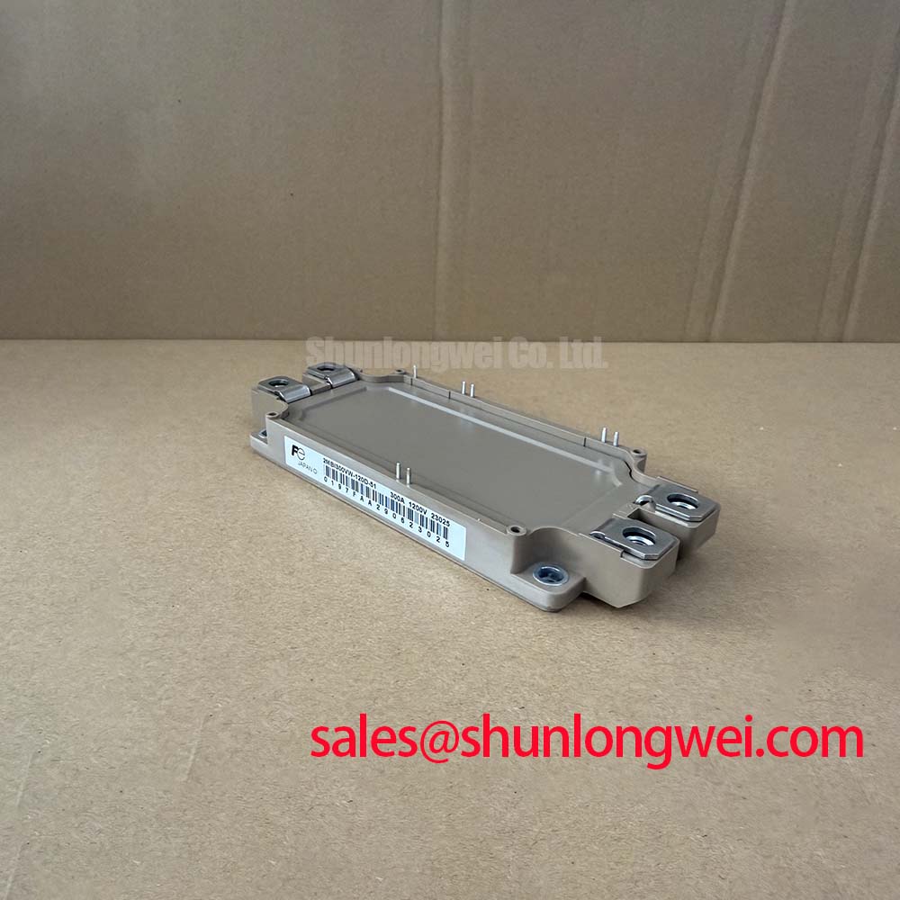
The M233 package provides a defined mechanical format for integration, but the heatsink assembly still determines much of the case to cooler thermal path. Before installation, check that the heatsink is clean, flat within the equipment’s mechanical specification, and free from burrs or particles. The module baseplate should sit evenly without being forced into alignment by the mounting hardware.
Thermal interface material should be applied consistently across the usable contact area. Avoid excessive compound, dry regions, trapped particles, and air pockets. The correct interface thickness depends on the selected material and the manufacturer’s application instructions; it should not be invented from the electrical rating. If the baseplate or heatsink has measurable curvature, correct the mechanical condition or follow the interface supplier’s approved compensation method rather than tightening one corner aggressively.
Use a controlled, progressive tightening sequence so that contact pressure develops evenly across the package. The required torque, fastener type, washer arrangement, and mounting sequence should come from the relevant mechanical documentation. After assembly, inspect for movement, uneven seating, interface extrusion, and abnormal temperature difference between parallel phases. Recheck the electrical isolation and gate connections after mechanical work, then commission the converter under controlled load while monitoring case temperature and switching waveforms.
For industrial electric forklifts and warehouse traction systems, compatibility should be confirmed against the original inverter topology, DC link range, braking strategy, cooling arrangement, terminal layout, and gate driver interface. The official specifications for this device are 1200 V VCES, 300 A IC at Tc = 80°C, 1.85 V typical VCE(sat), 6.0 V to 7.5 V VGE(th), 150°C maximum Tj, and 2-Pack M233 packaging. These values support an engineering review, while final acceptance depends on measured system performance and the original equipment documentation.