Content last revised on November 2, 2026
SKM300GB12V Thermal-Electrical Optimization: Cold-State Main Terminal Checks
Isolate the DC supply, verify that stored energy has discharged, and disconnect parallel circuit paths before placing a diode-check meter across the main terminals of the SKM300GB12V. Hold each gate at its corresponding emitter potential during the main-path check so that an unintentionally charged gate does not confuse the result. This Semikron IGBT module carries an official collector-emitter blocking rating of 1200 V at a junction temperature of 25°C and a nominal collector current of 300 A. (Manufacturer product page)
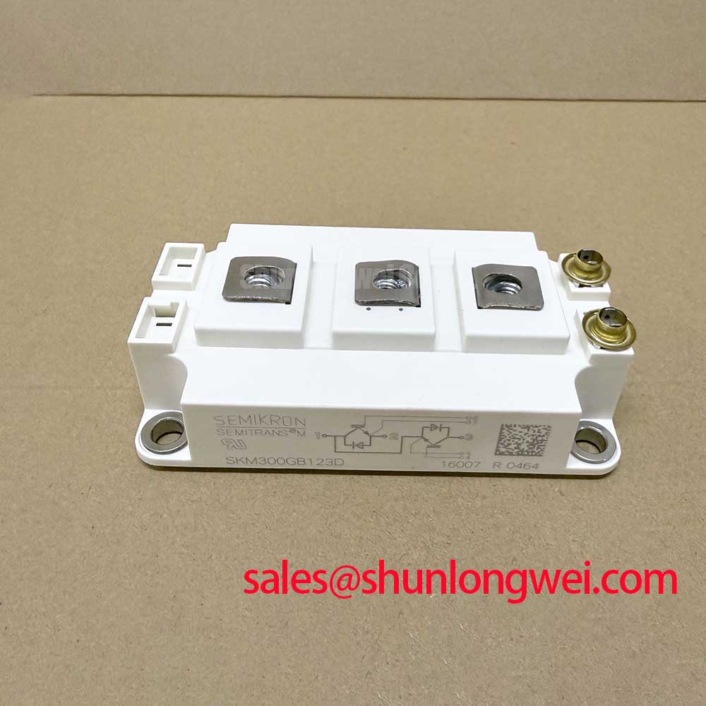
The module uses a half-bridge configuration in the SEMITRANS 3 housing. Its antiparallel diodes provide distinct paths for cold screening, while the gate connections require separate assessment. For maintenance planning, record terminal identification, instrument settings, module temperature, and circuit isolation status alongside the readings; those details make later comparisons useful when investigating an intermittent fault. (Manufacturer product page)
Measure each antiparallel diode in both probe directions, using the module circuit diagram to identify its emitter and collector connections. As an Engineering Recommendation, compare the two switching positions under the same conditions rather than assigning a universal forward-drop acceptance band. Unexpected continuity in both directions, an open indication in the forward direction, or a large difference warrants further isolation and investigation. Connected snubbers, driver resistors, and other semiconductor paths can influence the result, so distinguish the module measurement from the assembled circuit measurement. (Infineon community discussion)
Check gate-to-emitter behavior separately after removing the driver connection. A persistent low-resistance path deserves investigation, but a handheld meter provides only a preliminary screen for gross leakage or a short. It cannot establish blocking performance at rated voltage or demonstrate normal switching under load. Treat a repeatable cold test as one maintenance record, then use the equipment’s controlled commissioning procedure to assess operation after repair. (Infineon community discussion)
The official gate-emitter threshold range is 5.5–6.5 V, measured with collector current at 12 mA and gate tied to collector. That threshold describes the onset of conduction under the stated test condition. The official typical collector-emitter saturation voltage is 2.25 V at 300 A, junction temperature 150°C, and gate-emitter voltage 15 V, specified at chip level. A diode-check reading therefore addresses a different operating condition from the published conduction characteristic. (SKM300GB12V datasheet)
For thermal assessment, the manufacturer’s Rev. 5 datasheet specifies maximum junction-to-case thermal resistance of 0.11 K/W per IGBT; this value should govern calculations using that revision. The absolute maximum junction temperature is 175°C, while the same document gives a lower recommended operating-temperature range. As a Design Consideration, assess conduction loss, switching loss, case temperature, and the heatsink interface together when establishing the equipment’s continuous operating envelope. (SKM300GB12V datasheet)
During scheduled shutdowns, inspect the heatsink contact surface and thermal interface when disassembly is justified by the service procedure. As an Engineering Recommendation, choose inspection intervals from contamination exposure and temperature trends rather than inventing a fixed replacement calendar. Check for disturbed contact, uneven compound distribution, and mechanical loading from attached conductors. Use an interface material and application method qualified for the assembly, keeping compound away from threaded connections where it could affect tightening behavior. (Related Infineon mounting guidance for 62 mm modules)
Maintenance Note: Track terminal temperature rise at comparable load and inspect cooling passages before attributing a thermal alarm to the module. As an Engineering Recommendation, retain the load, ambient conditions, fan status, and measurement location with each inspection record so that changes can be compared meaningfully. (Manufacturer technical guidance)
Transient Dynamics & Electrical Design: Planar Busbar Geometry for SKM300GB12V
Reduce the commutation-loop area between the DC-link capacitor and the module by arranging outgoing and return conductors close together. As a Design Consideration, overlapping planar busbars can reduce stray inductance, provided their insulation and mechanical clearances suit the equipment. Include capacitor connections, terminal transitions, and the complete return path in the assessment; a compact section of busbar cannot compensate for a long connection elsewhere. (Infineon snubber considerations)
An Engineering Calculation can estimate the inductive contribution to turn-off stress through the relationship Vpeak ≈ VDC + Lσ × |di/dt|, with Lσ representing the effective commutation-loop inductance. This approximation helps connect conductor geometry and current fall rate to voltage overshoot. Establish the allowable peak from the module’s blocking boundary and the converter’s operating conditions, then verify the waveform with suitable probes. The acceptable inductance is a system result, determined by the actual switching behavior and layout. (Infineon snubber considerations)
Size a snubber around the measured transient and its repetitive energy duty. As an Engineering Recommendation, assess capacitor pulse capability, RMS current, connection inductance, and temperature rise together with any damping components. Position the snubber so its connections preserve the intended short current path. Shunlongwei’s technical guide, Mastering Power System Dynamics, provides related context for reviewing stray inductance and snubber behavior during a converter assessment. (Infineon snubber considerations)
Assess diode recovery during commutation alongside IGBT turn-on behavior. As a Design Consideration, reverse-recovery current adds to the switching event and can influence overshoot and loss. Keep surge-current terminology specific to the device: the antiparallel diode uses an IFSM rating under defined pulse conditions. Establish any permissible repeat event from the relevant transient thermal response and the starting temperature; a surge rating alone does not define a universal cooling or restart interval. (SKM300GB12V datasheet)
Evaluate cooling at the intended switching frequency and load profile. As an Engineering Recommendation, account for repetitive switching energy when comparing controller settings, then check airflow through the installed heatsink with cabinet restrictions and filter condition represented. Inspect fan operation and fin contamination during service. A thermal comparison is most useful when ambient temperature, airflow condition, and electrical duty are recorded together, allowing the maintenance team to distinguish cooling deterioration from a changed operating demand. (Manufacturer technical guidance)
Assembly Integrity & Layout Architecture: Gate Drive Loop Geometry for SKM300GB12V
Route each driver return to the corresponding auxiliary emitter connection shown in the module diagram, keeping that path separate from the external high-current emitter conductor. As a Design Consideration, this reduces shared external inductance that would otherwise alter the voltage seen by the driver during current transitions. Keep the gate conductor and its return close together, and inspect connector routing when a replacement assembly shows different switching behavior from the previous installation. (SKM300GB12V datasheet)
Review gate-loop damping using the complete driver path, including the module’s integrated gate resistance. As an Engineering Recommendation, adjust external resistance through controlled waveform evaluation, observing switching loss and voltage excursions together. Reverse-transfer capacitance, often written Cres, is a capacitance parameter; it is distinct from Miller plateau charge. An active Miller clamp provides a driver-side path for induced gate current, while collector-voltage active clamping serves a different protection function. (Manufacturer technical guidance)
If the converter uses a bootstrap-powered high-side driver, assess its charge budget against the switching pattern. As a Design Consideration, capacitor selection depends on gate charge, driver consumption, leakage, permitted supply droop, and the available recharge interval. Check initial charging and extended high-side conduction, including operating states that restrict replenishment. Evaluate the bootstrap diode’s reverse-voltage and recovery behavior against the selected driver circuit; its requirements belong to that circuit, rather than to a universal module prescription. (Infineon gate driver application note)
When comparing procurement options, treat the CM300HA-24E as a separate reference for an engineering comparison. As an Engineering Recommendation, establish circuit configuration, terminal mapping, mechanical fit, driver requirements, and thermal conditions before accepting a substitution. For electric material handling or forklift low-voltage traction inverter repairs, include the original power-stage architecture and conduction-loss requirements in that assessment; the application name alone cannot establish compatibility.
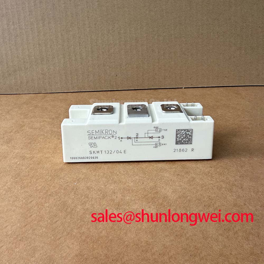
Keep product families distinct during documentation review. The manufacturer’s Semikron SEMIPACK® Thyristor / Diode Modules page concerns a different module family from this SEMITRANS IGBT. Its family designation provides no basis for transferring terminal arrangements or assembly instructions to the SKM300GB12V.
Before closing the enclosure, check that busbars seat without forcing the terminals and use calibrated tools with the applicable assembly instructions. As an Engineering Recommendation, inspect contamination and moisture around the control connections after exposure to changing temperatures, allow condensation to clear before energization, and retain the qualified gate wiring and protection settings in the service record. (Related Infineon mounting guidance for 62 mm modules)