Content last revised on October 9, 2026
CM200DX-24A Thermal Electrical Optimization with Low Inductance DC Bus Design
| Product | CM200DX-24A |
|---|---|
| Manufacturer | Mitsubishi Electric |
| Product category | IGBT Module |
| Package | Module |
| Rated voltage | 1200.0 V |
| Rated current | 200.0 A |
Inspect the DC bus connection and switching loop before applying power, paying particular attention to the physical distance between the CM200DX-24A, its DC link capacitor, and the commutation path. The module is specified at 1200.0 V and 200.0 A, but the voltage appearing across the device during switching is also influenced by stray inductance and current transition speed.
As a Design Consideration, a symmetrical laminated busbar or closely coupled planar arrangement can reduce unequal current paths and limit turn off overshoot. The basic relationship can be considered in-line: peak switching voltage rises with the DC bus voltage and the product of stray inductance and current change rate. The correct target is therefore established by the system designer through switching measurements, insulation coordination, and the allowable voltage margin of the complete converter.
Keep the positive and negative power paths closely coupled, avoid unnecessary conductor loops, and place any snubber network where it can control the local commutation loop rather than a remote section of the cabinet. Snubber capacitance is system dependent; select it only after examining switching waveforms, capacitor pulse capability, losses, and the converter operating frequency.
For an electric forklift or warehouse traction inverter, the service check should compare turn off voltage spikes at low, nominal, and regenerative operating conditions. A waveform that changes significantly with cable position or load current may indicate excessive parasitic inductance, an asymmetrical busbar path, or an unsuitable probe connection. Use a properly compensated differential probe and compare the result with the known good phase leg.
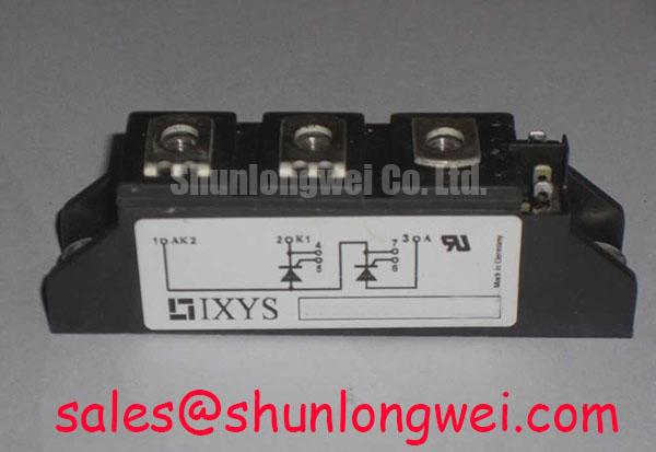
When the front end uses a separate rectifier or controlled rectifier stage, the associated power path should be assessed as one system. The MID200-12A4 may be reviewed as a related rectifier-stage component, subject to topology and electrical compatibility checks. In phase controlled systems, conduction angle affects input current shape and can increase harmonic content. The dq0 transformation described by Park Transformation can assist control engineers when separating active, reactive, and zero sequence behavior during inverter or motor-drive analysis.
CM200DX-24A Circuit Protection and Ceramic Substrate Stress Control
Check the mating surfaces before tightening the module: the heatsink should be clean, flat, and free of raised particles, while the module baseplate should sit without rocking or forced mechanical correction. Uneven contact pressure can create local thermal resistance and mechanical stress in the ceramic substrate, even when electrical connections appear normal.
The suggested TIM thickness values sometimes used in production work are Design Considerations, not Mitsubishi Electric specifications for this model. The practical objective is a continuous, thin, void controlled interface that fills microscopic surface irregularities without becoming a thick thermal barrier. Apply the selected material according to its supplier process window, then inspect the spread pattern on a controlled assembly sample before releasing the maintenance procedure.
Use a diagonal cross pattern when tightening the heatsink fasteners, bringing the assembly down progressively so that pressure is distributed across the baseplate. The correct torque is determined by the module mechanical drawing, fastener grade, heatsink design, and TIM supplier instructions. Do not substitute a general M5 torque value for the applicable Mitsubishi Electric mounting requirement.
Thermal verification should include the complete transient thermal path. The relevant question is not only the steady case temperature, but also how the transient thermal impedance network responds to acceleration, lifting, braking, and repeated load pulses in a traction inverter. Record case or heatsink temperature together with current and duty cycle, then compare the measured trend with the system thermal model.
⚠️ Maintenance Note: Schedule heatsink cleaning, inspect TIM condition during planned service, and monitor contact temperature trends while verifying that cabinet airflow remains unobstructed.
Assembly Integrity and Layout Architecture for CM200DX-24A
Complete the mechanical installation before finalizing control wiring: confirm heatsink seating, fastener sequence, terminal alignment, and clearance from adjacent conductive parts. The CM200DX-24A is a Module package with an official rating of 1200.0 V and 200.0 A; those values identify the component class but do not replace the converter’s switching, thermal, insulation, and protection validation.
Where a TIM process specifies a narrow application range, production engineering should control the material quantity, spreading method, storage condition, and cure or settling requirements. A commonly discussed 50 to 100 micrometer interface range may be used only as a process investigation reference, not as a model specific Mitsubishi Electric specification. Voids, contamination, baseplate curvature, and excessive mechanical correction should be treated as assembly variables requiring inspection.
Separate high current commutation conductors from gate or auxiliary control wiring wherever the mechanical design permits. If the installed version provides an auxiliary emitter or Kelvin connection, route that return independently from the power emitter path and verify the actual terminal definition against the applicable documentation. Do not assume every module variant has the same auxiliary terminal arrangement.
During troubleshooting, check whether gate loop noise changes when power cables are repositioned, then inspect the gate waveform at the module terminals rather than at the driver board alone. Gate resistance, dead time, driver supply behavior, and negative transients are system design variables. Any adjustment should be validated against switching loss, peak voltage, thermal response, and motor current quality.
For adjacent technology assessment, the article The 1200 V CoolSiC™ MOSFET Advantage in Three provides a useful comparison point for switching behavior in three phase conversion; it is not a replacement recommendation for this Mitsubishi Electric module. The related CM35MXA-24S can likewise be reviewed as a separate Mitsubishi Electric product for topology and rating comparison, with final interchangeability determined by the original equipment design.
For background on high voltage module construction and application boundaries, consult Mitsubishi Electric’s High Voltage HVIGBT Modules reference. Compatibility with forklift traction inverters, warehouse vehicle drives, or other industrial equipment should be established from the original circuit topology, terminal arrangement, cooling system, and measured operating conditions.