

Content last revised on October 21, 2026
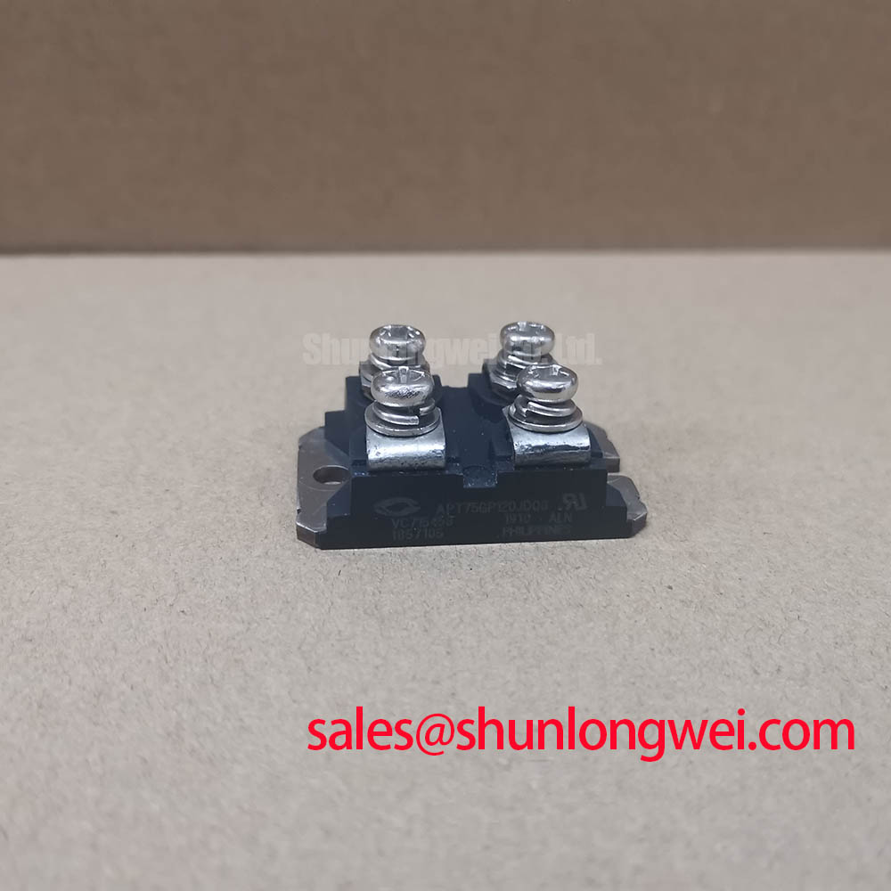
APT75GP120JDQ3 Incoming Inspection and Key Specifications
- With the DC link discharged and isolation verified, match the collector, emitter, and gate connections to the device terminal drawing before attaching test leads.
- Record cold diode-mode readings in both collector–emitter directions with the gate held at emitter potential, separating the device from parallel circuit paths where necessary.
- Inspect the mounting interface, terminal connections, and driver-return routing for contamination, mechanical strain, or disturbed contact surfaces.
- Check the gate-drive isolation arrangement and the equipment’s insulation-test procedure before applying any external test voltage.
The APT75GP120JDQ3 from Microsemi is an IGBT module with a 1200 V collector–emitter rating and a continuous collector-current specification of 75 A at a case temperature of 110°C. Incoming inspection should preserve those test conditions in the acceptance record rather than treating the current rating as an unconditional operating allowance.
| Parameter | Official Specification | Condition or interpretation |
|---|---|---|
| Collector–emitter voltage, VCES | 1200 V | Device blocking-voltage rating |
| Continuous collector current, IC | 75 A | Case temperature: 110°C |
| Collector–emitter saturation voltage, VCE(sat) | 2.4 V typical | Collector current: 75 A |
| Total switching energy, Ets | 3.3 mJ | Specified at 25°C; consult datasheet for complete switching-test conditions |
| Diode forward voltage, VF | 2.2 V typical | Forward current: 75 A |
| Junction-to-case thermal resistance, RthJC | 0.28°C/W | Junction-to-case thermal path |
A handheld meter cannot reproduce the stated saturation-voltage or diode-forward-voltage test at rated current. Its useful role is comparative: record polarity, instrument settings, device temperature, and circuit isolation, then investigate substantial differences against a known-good baseline. 💡 Bench Tip: Maintain ESD protection and hold the gate at emitter potential during cold diode checks so unintended gate charging does not distort the comparison.
APT75GP120JDQ3 Operational Boundaries: Evaluating Gate–Emitter Loop Routing
Trace the driver return to the emitter connection and identify every conductor segment it shares with load current. For this IGBT, gate–emitter is the correct control-terminal terminology; gate–source terminology belongs to MOSFETs. As a Design Consideration, shared emitter-path inductance can alter the effective gate voltage during switching and complicate interpretation of apparent gate ringing.
Keep the outgoing gate conductor and its driver return close together while separating their route from the main switching-current loop. If the equipment provides a dedicated auxiliary emitter connection, establish its identity from the terminal drawing before using it as the driver reference. A Kelvin emitter terminal must not be inferred from the model name or from a convenient nearby connection.
During controlled switching checks, measure gate–emitter voltage at the device-side connections with a suitable differential measurement arrangement. Compare the result with the driver-side waveform: disagreement can expose voltage developed along the return path, although probe placement and common-mode response also need checking. Gate damping should be selected against the measured oscillation, switching loss, and driver capability rather than copied from another assembly.
As an Engineering Recommendation, evaluate any negative turn-off bias against the permitted gate-voltage range and observed common-mode disturbance. Where a bootstrap driver is used, its recharge opportunities, capacitor charge balance, and charging-diode recovery belong to the driver assessment, not to an assumed feature of this module.
For replacement evaluation, the FS75R12KT3G is a separate comparison candidate, not an established direct replacement. Matching headline voltage and current does not establish matching circuit configuration, terminal assignment, mounting geometry, or driver requirements. Engineers assessing industrial inverter welders or medium-frequency induction-heating supplies should compare those interfaces with the original assembly before approving a substitution.
APT75GP120JDQ3 Operational Boundaries: Evaluating Overcurrent Protection and SCSOA Limits
Follow the collector-sensing path from the power terminal to the protection input, checking sensing polarity, return reference, and the driver’s response to a simulated fault. As a Design Consideration, desaturation protection needs to distinguish the normal turn-on transition from sustained abnormal collector voltage without leaving the device exposed beyond its documented short-circuit capability.
The 2.4 V typical VCE(sat) at 75 A is not a desaturation threshold. That threshold also depends on operating temperature, gate drive, sensing-diode behavior, and the protection circuit. Likewise, a universal short-circuit detection interval cannot be assigned from the blocking-voltage and current ratings. Establish protection timing from the applicable short-circuit safe operating area and the complete sensing-to-turn-off delay.
Protection assessment should distinguish a device turning on into an existing fault from a fault developing during conduction. Their initial conditions differ, so a satisfactory response in one case does not establish coverage of the other. Where the driver supports two-stage or controlled soft turn-off, evaluate whether it limits collector-voltage overshoot while clearing fault current within the permitted stress envelope.
Check terminal identity before reconnecting sensing wires, and examine creepage and clearance around the driver, terminals, and heatsink interface. The Comparative Tracking Index of PCB laminate materials explains a material property relevant to surface tracking; it does not establish this module’s insulation rating or the assembly’s required spacing. The 1200 V collector–emitter rating is also not a terminal-to-base insulation-test specification.
For broader terminology and diagnostic context, The Ultimate IGBT Knowledge Base provides supporting reading rather than a substitute for device-specific limits. On the bench, begin protection verification through the driver manufacturer’s approved low-energy test method rather than deliberately shorting an energized power stage.
APT75GP120JDQ3 Thermal-Electrical Optimization: Preventing Terminal Overheating
Measure accessible external power-joint resistance with a four-wire micro-ohmmeter after isolating parallel conduction paths. As an Engineering Recommendation, record probe locations and connection temperature so later measurements remain comparable; a resistance value taken across a different conductor length cannot reliably establish joint deterioration.
No universal micro-ohm acceptance threshold follows from this module’s electrical ratings. Compare the joint with the equipment’s approved connection specification and equivalent undisturbed connections. Examine conductor support, contact cleanliness, and fastening retention without transferring assembly force into the device terminals. Tightening torque and locking arrangements should follow the applicable mechanical instructions.
Thermographic inspection under a controlled, documented load can help distinguish localized joint heating from a broader cooling problem. Account for surface emissivity and reflected heat before interpreting an apparent hotspot. Correlate the image with current, case temperature, and resistance measurements instead of assigning a single cause from the image alone.
The 0.28°C/W junction-to-case thermal resistance characterizes only part of the heat-removal path. Interface condition and heatsink performance still affect operating temperature. Similarly, the 3.3 mJ switching-energy specification at 25°C should not be extended to every switching condition without considering the original test conditions and actual operating waveform.
When reviewing surrounding power hardware, treat the BSM75GP120 as a separate device requiring its own circuit and terminal assessment, not as an assumed front-end rectifier. Restore operation only after the affected connection shows stable comparative resistance and a repeatable thermal profile under the equipment’s approved acceptance procedure.