Content last revised on September 10, 2026
Incoming Benchtop Inspection: COG/TAB Anisotropic Conductive Film Integrity
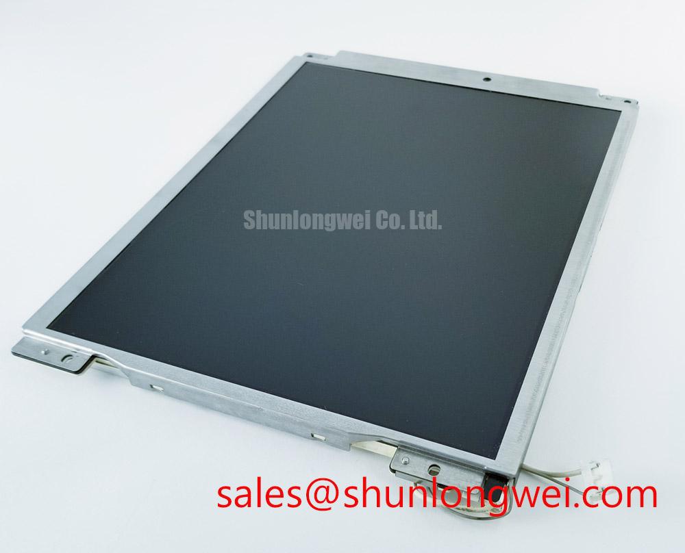
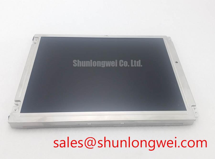
Begin the incoming inspection with the panel disconnected from all system power: record the nameplate marking, check the connector and flex tail for deformation, and examine the visible glass edge under controlled lighting before applying any signal. The unit identified as NL6448AC30-07 is a NEC TFT-LCD Display Module listed for industrial LCD and HMI use. The supplied factory information confirms the manufacturer, module category, and TFT-LCD construction, but it does not provide a complete public electrical pinout, optical specification, touch interface definition, or backlight drive table. Those items should be verified against the original NEC documentation for the exact revision.
| Model | NL6448AC30-07 |
| Manufacturer | NEC |
| Product category | Industrial Grade LCD/HMI Panel |
| Package or enclosure | TFT-LCD Display Module |
| Specification status | Official Factory Spec Verified for the supplied identification data |
A practical three-stage bench check can start with a full-field white image, followed by red, green, and blue fields, and then a black field. This procedure is a Design Consideration, not an NEC factory acceptance limit. Look for intermittent vertical lines, localized color loss, edge shadows, and areas that change when the flex assembly is gently observed without applying mechanical pressure. A display defect that appears only on one color field can require a comparison of the source signal, connector contacts, and panel-side bonding region rather than an immediate panel replacement decision.
The 45-degree flashlight inspection is also a useful qualitative method. With the display unpowered, shine a flashlight across the glass rather than directly into it. A continuous reflection pattern helps separate surface contamination and coating marks from dark regions that remain associated with the active matrix area. A localized shadow near a bonded edge may justify closer inspection of the COG or TAB region, but this observation alone does not establish a driver-bond failure. Confirm the result with a known-good signal path and, where possible, a second compatible test controller.
Do not infer an optical contrast ratio, anti-glare treatment, or sunlight performance from the product number. The requested value of greater than 500:1 at 50,000 lux is not included in the supplied factory parameter set. If this module is evaluated for a high-illumination diagnostic console, the integrator should obtain the exact contrast, luminance, surface treatment, and viewing-angle data from the original panel documentation. Ambient light, cover glass, bezel depth, and calibration settings can materially affect the result.
For sourcing decisions involving a related NEC display family, engineers can place the mechanical outline, connector position, active area, and timing requirements beside the documentation for NL10276BC16-06. This is a neutral comparison path only. Similar naming does not establish electrical, optical, or mechanical interchangeability.
Mitigating Gray-to-Gray Response Time Escalation during Cold-Start Machine Power-Up
Before a cold-start test, allow the complete display assembly and its controller to reach the intended chamber condition, then observe the first image transition with a stable test pattern. Gray-to-gray response behavior depends on the panel construction, liquid-crystal characteristics, drive waveform, controller timing, and temperature. The supplied information for NL6448AC30-07 does not state a GTG response-time value or a guaranteed thermal response curve, so no particular transition speed should be treated as an official rating.
At sub-zero temperature, a visible transition delay can be investigated by comparing the same gray pattern during cold start and after the assembly has stabilized. Use a photodiode or display measurement instrument when quantitative data is required. A visual impression may also include source timing instability, backlight warm-up behavior, image-processing delay, or an incorrect controller profile. Record the input format, frame timing, brightness setting, and controller firmware together with the optical measurement so that the panel is not evaluated in isolation.
The requested industrial thermal window of −30°C to +85°C must be treated as a verification target only unless it appears in the exact NEC datasheet for this revision. The same applies to perimeter sealant stability, storage limits, operating limits, and thermal-cycle endurance. These are system-level reliability matters requiring the original specification and the enclosure test plan. A display module should not be represented as suitable for a medical diagnostic instrument solely because it is categorized as an industrial LCD/HMI panel.
For a surgical-navigation or ultrasound-display evaluation, designers should verify the complete image chain from acquisition electronics through the display controller. A panel that shows a stable test image may still require a different timing configuration, data polarity setting, or image orientation setting in the final equipment. Where gray mapping appears abnormal, compare the controller configuration with the original system record before changing drive parameters. Avoid modifying panel drive waveforms without manufacturer documentation, because an apparently successful short bench test does not establish long-term panel reliability.
Backlight behavior should be examined separately from liquid-crystal response. The supplied factory data does not confirm whether the unit uses a particular backlight architecture, its LED current, its dimming input, its PWM range, or an integrated protection circuit. Therefore, statements about constant-current efficiency, flicker-free operation from 200 Hz to 1 kHz, a 50,000-hour MTBF, or open-load and short-load protection require an exact backlight datasheet or system schematic. When the original equipment uses a separate driver, test that driver and its fault output independently from the LCD signal path.
Controlled-Impedance Flex Routing for Signal-Integrity Evaluation
Identify the interface before connecting a replacement controller. The model identification supplied for NL6448AC30-07 does not include a confirmed LVDS or TTL designation, connector pin assignment, logic supply voltage, JEIDA or VESA mapping, clock polarity, or data-lane count. The system integrator should verify the required supply voltage from the original panel documentation rather than assuming a 3.3 V or 5.0 V interface.
A controlled-impedance routing plan is a Design Consideration when the verified interface uses differential signaling. If the source documentation specifies a 100-ohm differential path, maintain the intended reference structure through the board-to-flex transition, avoid unnecessary stubs, and keep paired conductors subject to consistent routing conditions. The final impedance is determined by the stack-up, conductor geometry, dielectric properties, connector transition, and flex construction. It should be validated by the system hardware team rather than inferred from the panel model.
Power sequencing also requires documentation-based verification. The proposed rise-time window of 0.5 ms to 10 ms is not identified as an official parameter in the supplied data. Confirm the panel logic rail, enable signals, reset behavior, backlight enable sequence, and allowable voltage relationships from the original NEC specification and the equipment controller schematic. During bench work, use current-limited power and verify the rail at the panel connector, not only at the controller output.
Split-screen artifacts, color-channel interchange, or a moving vertical band can arise from several conditions, including an incorrect JEIDA/VESA mapping, lane order errors, clock polarity mismatch, poor flex contact, inadequate signal integrity, or a controller profile intended for another panel. Compare the known-good waveform at the source and receiving connector with an oscilloscope or suitable high-speed measurement setup. A symptom should not be assigned to impedance mismatch without checking the complete signal path.
Hold time, setup margin, clock jitter, and temperature behavior belong to the verified interface design. The supplied factory information does not state numerical LVDS or TTL timing limits for this model. Designers should obtain those limits before selecting a transmitter or rewriting timing registers. The same caution applies to touch functions: no resistive or capacitive touch layer, glove sensitivity, water-touch performance, or touch-controller interface is confirmed by the provided product data. If the intended enclosure requires glove operation or wet-surface interaction, verify the separate touch assembly and controller specifications.
A related display solution such as NL10276BC30-24D may be reviewed as part of a broader display and backlight topology study. It should not be connected as a direct substitute until its interface, optical format, power requirements, and mechanical envelope have been matched against the target system.
💡 Pro Tip: Keep differential pairs under consistent routing conditions and confirm the actual panel mapping with a known-good image before changing controller timing.
Industrial Bezel Mechanical Envelope Tolerances & Mounting Screw Torque Optimization
Check the chassis opening, mounting-hole pattern, connector clearance, viewing-window position, and flex exit direction against the original assembly drawing before fastening the module. The supplied factory parameters do not include outer bezel dimensions, active-area dimensions, mounting-hole coordinates, glass thickness, or screw specification for NL6448AC30-07. These measurements must therefore be taken from the exact mechanical drawing or verified directly against the removed panel and its carrier.
Mechanical compatibility is more than matching the nominal diagonal size. A small difference in bezel shoulder position can obscure the active image, interfere with the flex tail, or place uneven pressure on the glass. Designers should provide clearance for connector insertion and service access while keeping the optical window aligned with the active area. The final enclosure tolerance is system-determined and should be checked with a dimensional inspection or a non-powered fit test.
The requested cross-pattern M3 fastening torque is not confirmed as an official NEC value in the supplied information. Treat it only as a possible assembly test value if the equipment manufacturer specifies M3 hardware and the carrier design supports it. The correct torque depends on the fastener, thread engagement, bracket material, washer arrangement, insert condition, and panel mounting design. Tighten progressively in a cross pattern only when the approved mechanical procedure requires it, and verify the result by checking the powered display for changes in uniformity.
Dark-field mura, edge brightening, or a localized shadow after installation should be investigated by comparing the module before and after mounting. Release the panel from the enclosure for a controlled comparison if the optical pattern changes with fastening. Do not assume that a visible defect is caused by the LCD cell itself; bezel pressure, bracket flatness, cable routing, contamination, and cover-window contact can all influence the observed image.
Surface performance also needs evidence from the exact part documentation. Anti-glare or anti-reflective treatment, contrast under direct sunlight, luminance stability, and viewing-angle behavior are not confirmed by the supplied factory parameter set. The display may be evaluated for high-precision surgical or ultrasound diagnostic equipment, but the medical equipment designer must separately validate optical performance, cleaning compatibility, enclosure sealing, electrical safety, EMC at the system level, and the applicable regulatory pathway.
For a structured review of panel interfaces, optical limits, and common integration issues, engineers may consult The Ultimate Guide to Industrial TFT-LCD Technology. The guide can support preliminary engineering review, while the exact NEC documentation remains the controlling source for model-specific limits.
When replacing a field display, retain the original controller configuration and compare the incoming module’s connector orientation, image timing, backlight connection, and mounting envelope before applying full system power. Any mismatch should be resolved through documented compatibility checks rather than by forcing the connector or adjusting unverified drive values.