

Content last revised on October 21, 2026
Assembly Integrity & Layout Architecture: Implementing Gate Driver Auxiliary Power Sequencing for 7MBR75U4B120-50
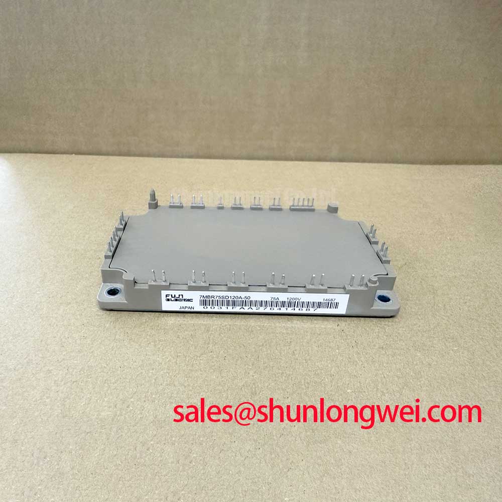
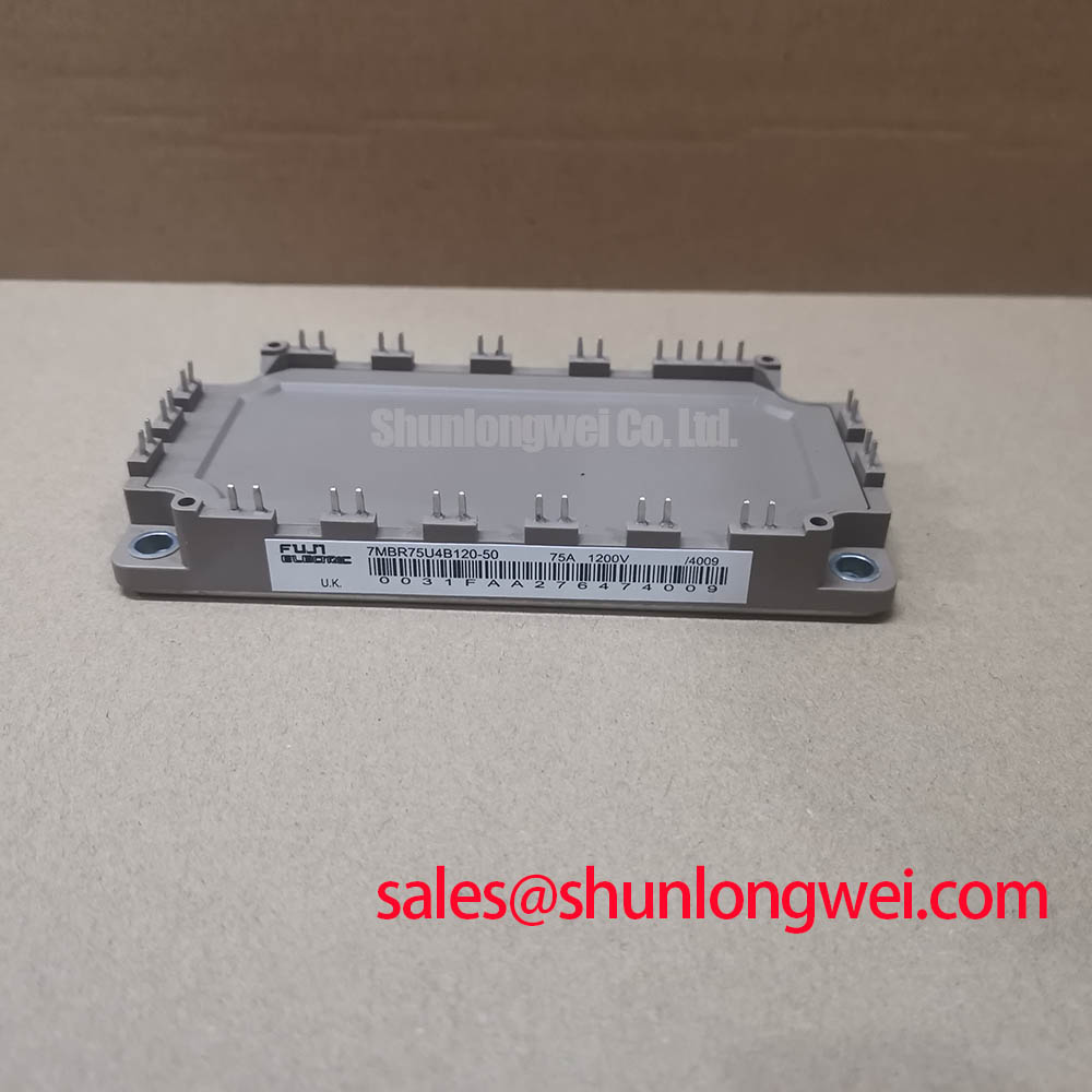
I check the gate-driver auxiliary supply and its undervoltage lockout response before allowing the main contactor to energize. For a replacement 7MBR75U4B120-50, this separates an upstream driver problem from a power-module problem without immediately exposing the replacement to DC-link energy. Trace the enable chain through the controller, driver supply, fault latch, and contactor command; a healthy auxiliary rail alone does not establish that the gates remain controlled throughout startup and shutdown.
Design Consideration: Observe gate-emitter voltage at the module connection using appropriately rated differential measurement equipment. Check the interval before enable, the transition into switching, and the decay of auxiliary power after disable. Where the existing driver uses negative off-state bias, verify that its intended bias is established before the DC link becomes active. The bias magnitude, startup delay, and undervoltage thresholds belong to the validated driver design, not to an assumed setting derived from this module’s voltage rating.
Keep the gate-drive outgoing and return paths closely coupled, and inspect whether repair wiring has enlarged their loop or moved them alongside switching power conductors. Such changes can alter gate disturbances during commutation. Maintain the equipment’s specified spacing between control wiring, power terminals, and grounded metalwork; layout acceptance depends on the complete assembly and its operating environment.
Engineering Recommendation: When reviewing repair alternatives, compare 7MBI100U4E-120 documentation against the original circuit before considering substitution. Circuit configuration, terminal assignments, driver requirements, mounting geometry, and thermal behavior must agree; a related model designation does not establish interchangeability. For electric material-handling equipment or forklift low-voltage traction repairs, first establish whether this voltage-class module actually matches the installed converter architecture rather than treating the application name as evidence of compatibility.
7MBR75U4B120-50 Circuit Protection & Reliability: Sizing Braking Resistors and Chopper Transistors
Trace the braking branch from the DC link to its switching device and resistor before changing protection settings. Establish from the equipment schematic which functions reside inside the power module and which belong to external circuitry. A DC-link rise during deceleration can involve the braking command, resistor circuit, energy-return path, or control response; it does not identify a failed chopper by itself.
Design Consideration: Braking-resistor evaluation should account for the energy released during deceleration, the interval between braking events, and the resistor’s permitted pulse and average loading. Examine the chopper’s switching and thermal limits alongside those conditions. Resistance, pulse duration, and protection thresholds are system-selected quantities. Increasing resistor power capacity alone does not demonstrate that the switching device or connecting conductors can tolerate the resulting duty.
The 75 A inverter current rating at an 80°C case temperature is an official electrical boundary with a stated thermal condition, not an unrestricted operating-current prescription. When assessing switching-frequency changes, account for switching loss, conduction loss, coolant or airflow conditions, and the measured case temperature. Higher switching frequency can increase semiconductor heating even when the displayed motor current remains similar. Check blocked filters and recirculating hot air before attributing a thermal trip solely to module deterioration.
Engineering Recommendation: Check desaturation sensing, fault propagation, and controlled turn-off against the driver and module documentation. Desaturation detection uses on-state collector-emitter behavior to identify abnormal conduction; its blanking interval must accommodate switching transitions without leaving excessive fault exposure. Soft turn-off can reduce abrupt current interruption, but its timing must remain compatible with the applicable short-circuit safe operating area. Do not establish short-circuit settings through uncontrolled fault trials.
During a topology review, the 7MBR100UB120 can be examined as a separate module reference for rectifier and inverter arrangements; its role in a front-end or auxiliary stage must follow its actual circuit diagram. Manufacturer documentation is available through the Fuji Electric Power Semiconductors Portal, which provides the appropriate starting point for device-specific operating limits and application guidance.
Preventing Spurious Faults: Thermal Interface Material Thickness Uniformity for 7MBR75U4B120-50
Remove old interface residue from the mating surfaces and inspect the heatsink contact area before seating the M633 package. Burrs, retained particles, or an uneven compound deposit can prevent consistent contact even when the mounting screws feel secure. Preserve surface finish during cleaning and keep debris away from terminals and control connections.
Design Consideration: Select the thermal interface material and application method for the actual mating surfaces and the material supplier’s instructions. The objective is to fill surface irregularities without creating an unnecessarily thick thermal barrier. Apply a controlled, repeatable deposit and assess its distribution using an approved assembly inspection method. A generic film-thickness range is not a substitute for the module mounting instructions or the chosen material’s behavior under clamping pressure.
Inspect heatsink flatness and assess module seating without forcing the package against a distorted surface. If an assembly does not sit correctly, identify whether contamination, surface damage, or incompatible geometry is responsible. Increasing screw load to compensate for poor seating can introduce mechanical stress without correcting the thermal path. Follow the specified tightening sequence and tool requirements for the actual mounting arrangement.
Field Alert: Do not tighten the module against an uneven heatsink or use mounting screws to pull a misaligned assembly into position.
Engineering Recommendation: Use the included NTC thermistor to evaluate the equipment’s temperature-feedback path, checking connector condition, harness continuity, and the controller’s configured resistance-temperature relationship. Its reading is not a direct measurement of peak junction temperature. If a trip appears only after warm-up, compare sensor behavior with independently measured accessible temperatures and the load history. In a bidirectional battery converter, where compatibility has already been established, evaluate heating during both charging and discharging rather than assuming equal thermal stress in each direction; avoid assigning a service-life extension without supporting test evidence.
7MBR75U4B120-50 Thermal-Electrical Optimization: Preventing Connection Stress During Practical Tuning
Check terminal hardware engagement and conductor alignment before applying final tightening torque. Use the module’s connection drawing to establish the permitted fastener arrangement rather than assuming that every visible connection accepts the same hardware. For screwed power connections, confirm that the fastener clamps the intended stack instead of bottoming out; where connections use another attachment method, follow that interface’s assembly requirements.
Design Consideration: Support heavy conductors independently so their weight and vibration are not carried through the module connection. Busbars should meet the terminals without being levered into alignment. Washer selection, thread engagement, and tightening torque must suit the documented joint arrangement. These external checks address avoidable connection stress without assuming a particular internal leadframe or proprietary joining structure.
Inspect the power-loop geometry after any busbar repair. Minimize unnecessary loop area to limit turn-off inductive overshoot, while preserving required electrical spacing and mechanical support. A laminated busbar can reduce loop inductance when its outgoing and return current paths are appropriately arranged, but its effectiveness depends on the complete connection geometry. Verify collector-emitter transients with suitable instrumentation under controlled operating conditions and compare the measured peaks with the module’s 1200 V blocking limit, allowing an appropriate design margin.
Engineering Recommendation: If temperature or fault behavior changes after tightening or cable movement, isolate the assembly and examine contact condition, conductor restraint, and measurement connections before condemning the module. Compare equivalent phases under matched conditions; unequal results can guide investigation but do not establish a unique failure mechanism. The Power Electronics Masterclass provides broader context for connecting gate-drive behavior, parasitic inductance, and thermal management.
Record the installed hardware arrangement, interface-material application, driver checks, and controlled-load observations in the repair record. Retain waveform captures that show gate behavior and collector-emitter overshoot alongside the test conditions. Those records make a later intermittent fault easier to distinguish from a changed mounting joint, altered wiring route, or cooling-system problem.