
Content last revised on September 10, 2026
Addressing Thermal Stress in Industrial Automation
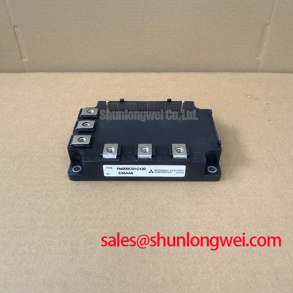
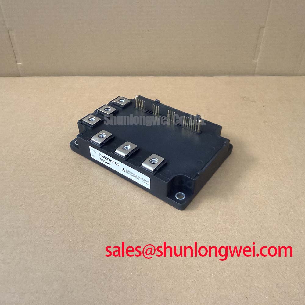
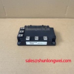
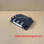
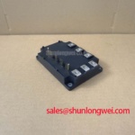
How do design engineers prevent substrate solder fatigue in high-duty industrial motor drives? The PM200CG1C120 provides a direct solution. By eliminating substrate solder joints through a resin-insulated metal baseplate, this module enhances thermal cycle lifetime in demanding environments. Top Specs: PM200CG1C120 | 1200V | 200A | Rth(j-c)Q 0.10 K/W. Key benefits: Solder-free thermal design, integrated gate drive protection. It resolves failure risks by incorporating localized over-temperature detection on the chip surface. For variable frequency drives requiring high thermal margins, this 1200V IPM is the optimal choice.
Frequently Asked Questions
Resolving Engineering Integration and Reliability Concerns
What is the primary benefit of its resin-insulated design?
Enhanced long-term reliability by eliminating solder fatigue. By removing the traditional solder joint between the substrate and baseplate, the module prevents thermal stress-induced delamination under heavy cyclic loads.
How does the low Rth(j-c)Q of 0.10 K/W impact thermal design for 20kHz switching?
A lower thermal resistance of 0.10 K/W ensures rapid heat dissipation from the junction to the case. This minimizes junction temperature rise during high-frequency switching, allowing for more compact heatsink designs without exceeding thermal boundaries.
Why is the integrated chip-surface over-temperature detection superior to case thermistors?
The built-in sensor directly monitors the temperature of the CSTBT™ silicon die rather than the baseplate. This allows the module to trigger shutdown protection at 150°C within milliseconds, preventing catastrophic failure from localized thermal overloads.
Is an external gate driver power supply required for the PM200CG1C120?
Yes. While the module integrates drive control and protection circuit logic, it requires an external control supply voltage VD of 15V (applied across VUP1-VUPC, etc.) to power these internal components.
Key Parameter Overview
Decoding the Specs for Enhanced Thermal Reliability
| Parameter Symbol | Technical Specification Value | Operational Condition / Detail |
|---|---|---|
| VCES | 1200V | Collector-Emitter Voltage (VD = 15V, VCIN = 15V) |
| IC | 200A | Continuous Collector Current (TC = 25°C) |
| VCE(sat) | 1.3V (Chip) / 1.95V (Terminal) | Collector-Emitter Saturation Voltage (IC = 200A, Tvj = 25°C) |
| Rth(j-c)Q | 0.10 K/W (Max) | Thermal Resistance, junction-to-case (IGBT, per element) |
| Visol | 2500 Vrms | Isolation Voltage (AC 1 minute, 60Hz, sinusoidal) |
| SC | 400A | Short-Circuit Trip Level (-20°C ≤ Tvj ≤ 125°C, VD = 15V) |
Download the PM200CG1C120 datasheet for detailed specifications and performance curves.
Technical & Design Deep Dive
Analyzing Resin Insulation and Gate Drive Integration for Long-Term Reliability
To fully understand the module, engineers must evaluate how physical design constraints dictate performance. Consider the thermal resistance Rth(j-c)Q of 0.10 K/W. In power electronics design, thermal resistance acts like a highway traffic bottleneck. A lower resistance value is analogous to a wider multi-lane highway, allowing heat energy to transfer from the silicon junction to the heatsink with minimal congestion. This keeps the internal temperatures safely below the limits.
Similarly, the collector-emitter saturation voltage VCE(sat) of 1.3V at the chip level can be compared to pressure drop in a water pipe. A lower saturation voltage means less friction (voltage drop) during conduction, directly translating to fewer conduction losses. Understanding why Rth matters is essential for calculating system efficiency, as detailed in the engineer's ultimate guide to IGBT modules.
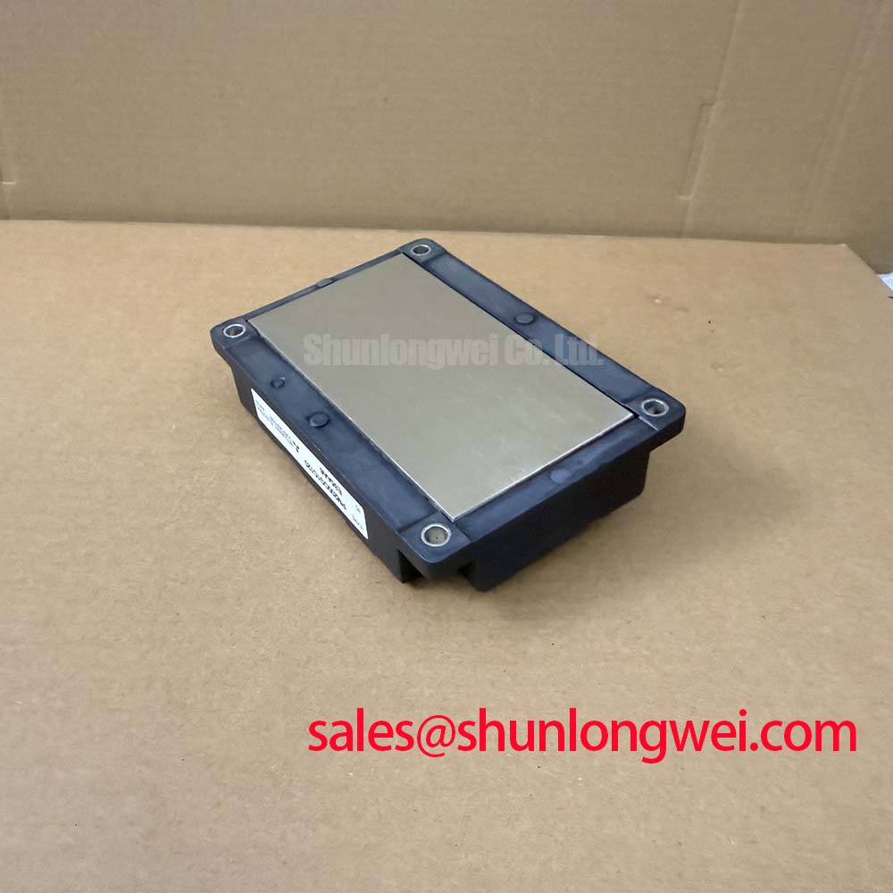
The G1 series package replaces the traditional solder layer between the substrate and the metal baseplate with a resin-insulated design. Because thermal cycling causes materials with different thermal expansion coefficients to expand and contract at different rates, eliminating the solder joint mitigates the risk of delamination. By combining this mechanical advantage with the 7th Generation CSTBT™ chip design, switching losses are reduced, and overall system lifetime is significantly extended.
Application Scenarios & Value
Optimizing Motor Drives and Inverters with Built-in Diagnostics
In high-torque industrial motor drives operating under frequent load changes—such as conveyor belts and gantry cranes—the power stage experiences constant cycling between high surge currents and idle states. Operating a 1200V system under these conditions creates substantial thermal swings. Implementing the PM200CG1C120 in a Variable Frequency Drive (VFD) or servo drive ensures the module accommodates these fluctuations without degrading the internal connections.
Furthermore, systems targeting compliance with strict electromagnetic compatibility and grid standards like IEC 61800-3 benefit from the integrated drive circuitry, which limits high-frequency noise generation. The module's built-in short circuit protection trips at 400A, shielding the inverter from phase-to-phase shorts. For designs incorporating three-phase inverters, proper IGBT thermal management remains a key design requirement to maximize the module's 200A current-carrying capacity.
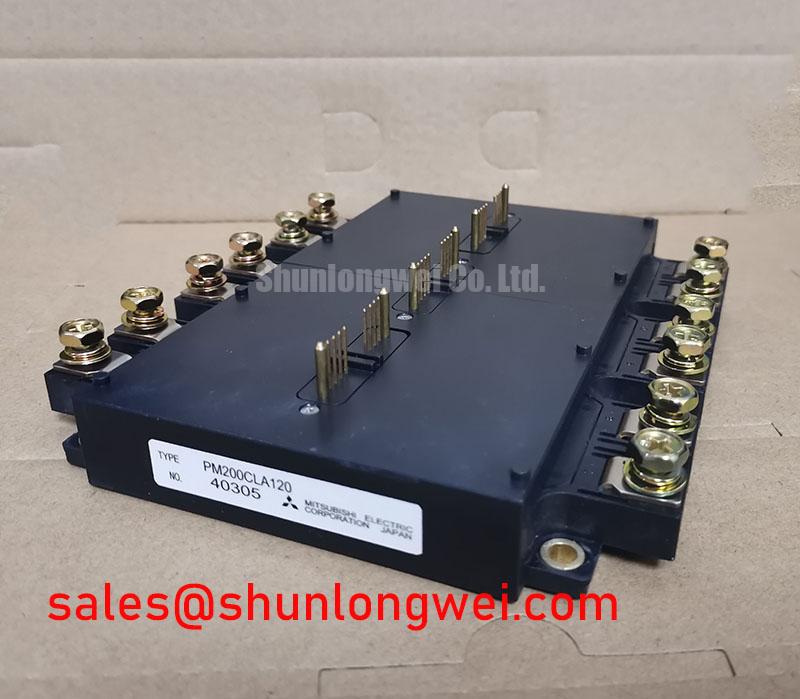
For systems requiring comparable voltage ratings but configured for different power levels, the related PM150CSD120 offers alternative current options, while the related PM200CLA120 serves as a baseline comparison for legacy designs. Implementing these intelligent modules helps streamline layout complexities in industrial UPS applications.
As the industrial sector transitions toward highly integrated power electronics, selecting modules with integrated protection logic and solder-free packaging becomes a strategic imperative. This approach minimizes external part counts, decreases physical footprint, and shifts design focus from discrete protection design toward higher-level system efficiency and long-term grid integration goals.