

Content last revised on September 13, 2026
Benchtop Waveform Tuning: Mitigating Stress via Baseplate Convexity Compensation and Screw Mounting of CM50MX-24A
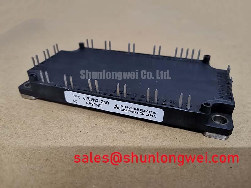
Before energising a replacement, isolate the traction inverter, inspect the module base and terminals, and verify the marked electrical boundary: CM50MX-24A by Mitsubishi Electric is specified as a 1200 V, 50 A IGBT module in a module package. These are official product specifications; gate-drive conditions, switching frequency, thermal limits, pin assignments, and mechanical dimensions must be confirmed from the original equipment documentation before installation.
| Manufacturer | Mitsubishi Electric |
| Part number | CM50MX-24A |
| Device category | IGBT Module |
| Rated voltage | 1200.0 V, Official Specification |
| Rated current | 50.0 A, Official Specification |
| Package | Module, Official Specification |
Place the module on a clean, flat heatsink and check that the mating surfaces are free from burrs, metal particles, and hardened thermal compound. The supplied data identifies the package as a module but does not provide a manufacturer-approved thermal interface thickness, mounting torque, screw sequence, or baseplate flatness tolerance. Those values are therefore system-level design considerations rather than CM50MX-24A factory specifications.
For a repair bench evaluation, apply the selected thermal interface material as a uniform, thin layer and avoid trapped air pockets. If the baseplate shows measurable curvature, the mechanical engineer should evaluate compensation through the heatsink surface, clamping arrangement, or approved interface material. Do not force the module flat with uneven screw pressure. Start each fastener by hand, bring the screws into light contact in a diagonal sequence, and complete tightening progressively while checking that the module remains seated.
During commissioning, monitor collector-emitter waveform, gate signal quality, heatsink temperature, and current sharing under the actual regeneration profile. A braking chopper or high-power resistor can create repeated thermal pulses, so the test plan should include acceleration, deceleration, and fault-clearance events. The inverter designer must determine the allowable junction-temperature recovery window from the complete power-stage thermal model and the applicable Mitsubishi documentation.
Transient Dynamics & Electrical Design: Planar Symmetrical Busbar Geometry on CM50MX-24A
Confirm every power and control terminal against the original schematic before connecting the replacement. The available product data does not establish a universal pinout for this page, so terminal identity should be verified by the equipment drawing and a continuity check performed with the module isolated. A cold resistance comparison with a known-good unit can help identify an abnormal short or open condition, but a meter reading alone cannot validate switching performance.
In the commutation loop, stray inductance converts rapid current change into voltage overshoot. The engineering relationship can be described in the switching test as the peak terminal voltage rising with DC-link voltage and the product of stray inductance and current slew rate. Designers should minimise the high-current loop area with short, broad, symmetrical busbars, then verify peak voltage at the module terminals using an appropriately rated differential probe. Any target such as a specific nanohenry value is system-determined and must be validated against the actual layout and switching conditions.
Snubber selection should follow measured ringing energy, switching frequency, capacitor pulse capability, and resistor heating rather than a generic capacitor value. Keep creepage and clearance suitable for the working voltage, pollution environment, insulation system, and enclosure. Busbars need mechanical restraint against vibration, with fastening selected so that electrical contact pressure is maintained without distorting the module terminals.
For background on the switching behaviour of resonant and half-bridge equipment, consult Resonant Topologies in Home Appliances. Mitsubishi Electric’s Power Semiconductors and High-Power Modules resource should also be checked when confirming device-family application information.
Preventing Spurious Faults: Kelvin Emitter Connection Guidelines for CM50MX-24A
If the equipment uses an auxiliary emitter or gate-return connection, keep the low-level driver return separate from the main high-current emitter path until the intended reference point defined by the original circuit. Shared copper can introduce common impedance coupling during turn-on and turn-off, producing apparent gate disturbance, oscillation, or protection trips. This is a design consideration, not a confirmed internal feature or guaranteed connection scheme for this model.
Route the gate loop tightly with its return, keep it away from high-current commutation conductors, and verify the signal directly at the module terminals rather than only at the driver output. When a fault appears during regenerative braking, compare gate-to-emitter voltage, collector-emitter voltage, and phase current with a known-good switching event. The system engineer should decide whether the observed disturbance comes from layout coupling, driver timing, protection interaction, or an external load condition.
⚠️ Field Alert: Disconnect the DC link and wait for the equipment’s verified discharge procedure before touching terminals or removing control and power connectors.
Field Diagnostics & Commissioning: High-Frequency Common-Mode Bearing Current in CM50MX-24A Topologies
Long motor cables, motor-frame bonding, and inverter common-mode paths can influence bearing-current symptoms in forklift traction systems, but the module alone does not establish the cause. During commissioning, inspect cable shielding and bonding continuity, compare motor-end and inverter-end reference potentials, and use a suitably rated oscilloscope setup to examine common-mode voltage and terminal ringing.
Transmission-line reflection can increase motor-terminal stress when cable impedance and termination are mismatched. Rather than assuming a fixed spike multiplier, designers should measure the installed cable response and select any output filter, choke, or dv/dt network from the motor insulation rating, cable length, switching profile, leakage-current limits, and thermal duty. Filter changes can alter control-loop behaviour and braking performance, so the complete traction system requires functional testing under loaded and unloaded conditions.
For a procurement or emergency replacement review, CM50DY-28H may be evaluated as a separate, objectively compatible device candidate only after checking voltage class, current rating, circuit topology, terminal arrangement, mechanical fit, gate-drive requirements, and thermal design. Mitsubishi Electric’s Global Semiconductor Device Technologies information can support documentation checks, while final interchangeability remains the responsibility of the equipment designer.