
Content last revised on February 7, 2026
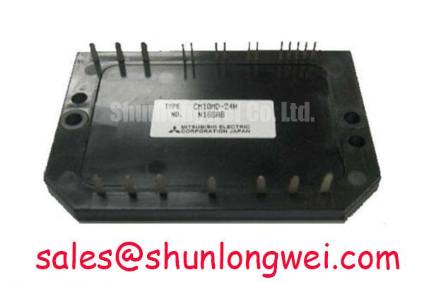
An Engineer's Look at the CM10MD-24H Dual IGBT Module
Introduction to a Workhorse Component
Reliability and Performance for Mainstream Power Applications
The CM10MD-24H is a dual IGBT module from Mitsubishi's H-Series, engineered for reliability in low-to-medium power switching applications. It integrates two IGBTs in a single, compact package, featuring core specifications of 1200V and 10A. This module is distinguished by its robust thermal design and proven performance, offering benefits like simplified thermal management and enhanced operational stability. For engineers designing cost-sensitive servo drives or auxiliary power supplies that require proven, dependable components over cutting-edge switching speeds, this module presents a compelling solution. For systems where a balance of cost and proven reliability is paramount in the sub-1kW power range, the CM10MD-24H provides a thermally efficient and established platform.
Application Scenarios & Value
Achieving System-Level Reliability in Motor Control and Power Conversion
The primary value of the CM10MD-24H lies in its deployment in applications where long-term reliability and straightforward design are critical decision factors. A key engineering challenge in compact industrial equipment, such as a small-scale Variable Frequency Drive (VFD), is managing heat within a constrained enclosure. The module's specified thermal resistance (Rth(j-c)) directly facilitates effective heat dissipation, allowing for more compact heatsink designs without risking thermal overload during cyclical operations. This makes it a suitable choice for small motor drives, uninterruptible power supplies (UPS), and servo drives where predictable performance is more critical than achieving the absolute highest switching frequency. While the CM10MD-24H is optimized for 10A applications, for systems demanding higher current handling in a similar package, the related CM50DY-24H offers a step-up in power capability.
Key Parameter Overview
Decoding the Specs for Robust and Predictable System Design
The technical specifications of the CM10MD-24H are tailored for durable performance in its target applications. The parameters outlined below are foundational to its operational reliability and thermal stability.
| Absolute Maximum Ratings (Tj = 25°C unless otherwise noted) | |
| Collector-Emitter Voltage (Vces) | 1200V |
| Collector Current (Ic) | 10A |
| Gate-Emitter Voltage (Vges) | ±20V |
| Total Power Dissipation (Pc) | 78W |
| Electrical Characteristics (Tj = 25°C) | |
| Collector-Emitter Saturation Voltage (VCE(sat)) | 3.5V (max) at Ic = 10A |
| Short Circuit Withstand Time (tsc) | 10µs |
| Thermal and Mechanical Characteristics | |
| Thermal Resistance, Junction to Case (Rth(j-c)) per IGBT | 1.6°C/W (max) |
| Isolation Voltage (Visol) | 2500V (AC, 1 minute) |
Download the CM10MD-24H datasheet for detailed specifications and performance curves.
Technical Deep Dive
Analyzing Thermal Performance and Its Impact on Application Reliability
A critical parameter for power module longevity is its Thermal Resistance, Junction-to-Case (Rth(j-c)). For the CM10MD-24H, the specified maximum of 1.6°C/W per IGBT is a key indicator of its thermal design quality. This value quantifies how effectively heat generated at the semiconductor junction is transferred to the module's baseplate. Think of it as the thermal 'bottleneck' of the device; a lower value signifies a more efficient heat evacuation path. This efficiency simplifies the engineer's task of thermal management, potentially allowing for a smaller, lower-cost heatsink or improved performance margins in high-ambient-temperature environments, directly contributing to the overall reliability and lifespan of the end system.
Frequently Asked Questions (FAQ)
How does the dual (2-in-1) configuration of the CM10MD-24H benefit a power circuit design?
The dual configuration, which integrates two IGBTs typically arranged as a half-bridge, simplifies the layout for single-phase inverters or chopper circuits. This reduces parasitic inductance compared to using two discrete components, improves thermal symmetry, and streamlines assembly, leading to a more compact and reliable power stage.
What is the engineering significance of the 10µs short-circuit withstand time?
The 10µs short-circuit withstand time is a crucial reliability metric. It defines the maximum duration the IGBT can endure a direct short-circuit condition before catastrophic failure. This gives the system's protection circuitry, managed by the gate driver, a defined time window to detect the fault and safely shut the device down, preventing cascading failures and enhancing overall system robustness.
To evaluate the CM10MD-24H for your design or to inquire about its integration into your application, please contact our technical sales team for further information.