



Content last revised on September 30, 2026
Preventing Spurious Faults: Short Circuit Detection in PM75CL1A120
| Hardware specification | PM75CL1A120 |
|---|---|
| Manufacturer | Mitsubishi Electric |
| Product category | Intelligent power module |
| Package | Mitsubishi IPM module |
| Rated voltage and current | Numerical ratings are not established by the supplied specification information; verify against the original Mitsubishi Electric datasheet and module marking. |
Capture the PM75CL1A120 fault output alongside phase current and DC bus voltage during the event that stops the inverter. A fault reported during acceleration calls for a different investigation from one appearing as the drive is enabled: compare the command sequence, current waveform and fault timing with a known working installation before disturbing the power connections.
Short circuit protection depends on both the module and the surrounding control circuit. Use the equipment schematic to identify the fault output, its supply and the controller response; then check whether the controller removes switching commands when the fault is asserted. Do not assign a desaturation threshold, detection time or short circuit withstand period to this module from a general IPM design rule. Those limits need the applicable Mitsubishi Electric specification and its stated test conditions.
A nuisance trip can also coincide with noise coupled into a control lead. As a Design Consideration, inspect the control harness return path, shielding and separation from the power conductors, then compare signals at the module connector and controller input with an isolated measurement setup. If a switching edge appears on the fault line, investigate grounding and routing without assuming that the fault circuit is defective. Gate off bias and soft turn off behavior likewise belong to the documented module and drive interface; verify their implementation rather than applying a generic negative gate voltage or adding an external turn off stage.
Mitsubishi Electric’s DIPIPM bootstrap circuit design note explains supply charging and voltage monitoring considerations for DIPIPM circuits. It is useful background when tracing a bootstrap powered control supply, but it does not establish the PM75CL1A120 pinout, protection timing or supply limits. Match any observed control supply behavior to this module’s own documentation and the host drive schematic.
Field Diagnostics and Commissioning: Thermal Response of PM75CL1A120
Log heatsink temperature and phase current through the load pulse that precedes a thermal fault. A cool heatsink immediately after a brief overload does not prove that junction temperature stayed within its limit: heat takes time to reach the case and sensor. Compare the fault record with the operating cycle, cooling airflow and a known working unit before attributing the trip to the module.
For a pulsed load, an Engineering Calculation can estimate peak junction temperature by applying the documented transient thermal impedance to the pulse loss and adding the resulting temperature rise to the starting case temperature. That calculation requires the correct loss data, pulse history and PM75CL1A120 thermal impedance information. Without them, a numerical junction temperature margin would be conjecture. Repeated pulses also require attention to the temperature left by earlier events; treating each pulse as if the module had fully cooled can understate the peak.
Inspect the heatsink contact surface, mounting condition and thermal interface material when the recorded temperature rise has changed from the equipment’s established baseline. Check fan operation under load and remove dust from the airflow path. Switching frequency affects loss, but no frequency range or derating curve for this module is established here; use measured operating conditions and the relevant manufacturer limits when assessing a change to the drive setup. In a hot enclosure, verify cooling at the highest expected ambient condition rather than relying on a workshop test at room temperature.
Maintenance Note: Isolate and discharge the DC bus before touching module terminals, then check terminal tightness and heatsink airflow during scheduled service.
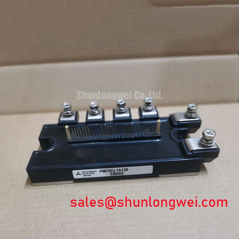
Where a replacement is being evaluated, compare the marked part, mounting interface, terminal arrangement, control connector and documented electrical limits. The PM20CVL060-33 can be reviewed as another Mitsubishi module reference, but it is not established as a direct substitute for PM75CL1A120. Mechanical resemblance alone cannot settle control or power circuit compatibility.
Transient Dynamics and Electrical Design: Braking Loads Around PM75CL1A120
Measure DC bus voltage during commanded deceleration and compare it with the brake command and phase current traces. A rising bus can reflect regenerated motor energy, a braking circuit that has not engaged as expected, or a load profile outside the equipment’s intended operating conditions. Trace the braking path on the host schematic before assigning any braking function to the PM75CL1A120; the supplied product information does not establish an internal braking IGBT.
As a Design Consideration, assess a braking transistor and resistor against the energy returned by the actual motor and load, the permitted bus voltage excursion, and the resistor’s pulse and cooling limits. Selection of those parts is a system design decision, not a rating that can be inferred from the IPM model number. During commissioning, verify the worst relevant deceleration condition with suitable isolated instruments and confirm that measured switching peaks remain within the documented limits of every affected component.
Keep the power loop compact to reduce inductive overshoot during switching, while maintaining the clearances required by the equipment design. Examine terminal condition, DC bus connections and the braking circuit’s physical routing if a fault appears only during deceleration. A bus overvoltage trace supports further investigation; by itself, it does not identify a failed IPM, resistor or controller.
For electric material handling equipment, including a forklift traction inverter, compatibility also depends on the actual DC bus architecture, motor duty and braking arrangement. Treat that equipment class as a possible evaluation context, not as evidence that this module was specified for a particular vehicle.
PM75CL1A120 Circuit Protection and Reliability at Elevated Sites
Record the DC bus voltage, switching overshoot and installation altitude when evaluating a drive that repeatedly faults at a high elevation. First separate measurable electrical stress from an unexplained failure: inspect cooling, condensation exposure, terminal condition and fault logs, then compare the waveforms with the equipment’s documented limits.
Altitude can affect cooling and insulation coordination, while terrestrial radiation is a separate reliability consideration for power semiconductors. Neither an altitude derating rule nor a single event burnout failure rate for PM75CL1A120 is established by the supplied product information. A defensible FIT estimate would require device specific characterization, an operating voltage profile and an applicable radiation environment model; it cannot be calculated from the model name or a site elevation alone.
As a Design Consideration, control DC bus overshoot and verify thermal performance under the installation’s actual ambient and airflow conditions. Where long service intervals drive the evaluation, record operating conditions and maintenance findings so changes can be compared with a baseline. The Wide Bandgap Revolution article provides broader power semiconductor technology context, but it is not a qualification record or lifetime prediction for this Mitsubishi Electric IPM.
Inspect for moisture or condensation before returning the drive to service after a shutdown. If insulation performance is in question, follow the equipment maker’s approved test procedure with the module connected or disconnected as that procedure requires; a system level insulation result must not be represented as an independent certification of the PM75CL1A120.